- Envisat
- Mission
- Envisat Overview
Envisat Overview
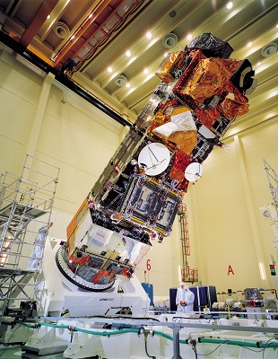
In March 2002, the European Space Agency launched Envisat, an advanced polar-orbiting Earth observation satellite which provided measurements of the atmosphere, ocean, land, and ice.
The Envisat satellite had an ambitious and innovative payload that ensured the continuity of the data measurements of the ESA ERS satellites. Envisat data supported Earth science research and allowed monitoring of the evolution of environmental and climatic changes. Furthermore, the data facilitated the development of operational and commercial applications. Together with its predecessors, ERS-1 and ERS-2, the Envisat mission deeply contributed to expanding our knowledge in the Earth sciences and to develop operational applications related to environmental monitoring.
The Polar Platform (PPF) and Envisat Programmes emerged from two basic roots:
- The development of a multi-mission Polar Platform for future Earth observation missions, initially started as an element of the Columbus Space Station Programme
- The Polar Orbiting Earth Observation Mission (POEM-1), initially conceived as a combined mission with instruments for scientific application, research, and operational meteorology. This mission, based on the Polar Platform, was the successor of ERS.
The PPF development activities started in 1990, following the selection of the Polar Platform as a derivative of SPOT 4, by the ESA council. An industrial proposal was submitted and evaluated at the end of 1990 and implemented starting in early 1991. Since then, the following major external programmatic events took place:
- Deletion of multi-mission requirements and related activities for cost saving reasons
- Splitting of the first mission POEM-1 into Envisat (the environmental mission) and Metop-1 (the meteorological mission) in mid-1993
- Several iterations on cost savings/de-scoping actions executed in mid-1993, early 1994, and the end of 1995 to reduce overall programme costs in industry and ESA.
Final industry negotiations were completed in mid-1995 and the PPF phase C/D contract for the development and integration of the Polar Platform with the Envisat instruments was signed in July 1995.
The mission and development of the payload instruments for Envisat started after the split of POEM-1 into Envisat and MetOp-1 at the Ministerial ESA council meeting in December 1993.
The eight-tonne satellite orbited Earth more than 50,000 times over 10 years – twice its planned lifetime. The mission delivered thousands of images and a wealth of data used to study the workings of the Earth system, including insights into factors contributing to climate change.
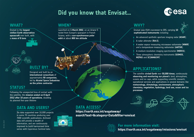
Infographic
The Envisat mission is summarised in this infographic:
Satellite Design
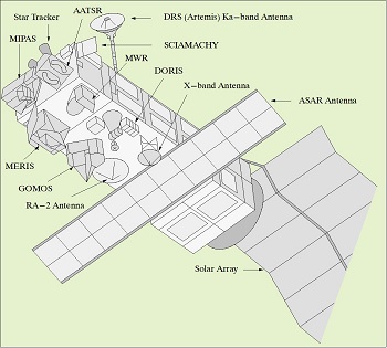
The major driver for the Polar Platform/Envisat satellite configuration was the need to maximise the payload instrument mounting area and to meet the viewing requirements within the constraints of the Ariane 5 fairing and interfaces. Additionally, the configuration was also driven by the reuse of the SPOT Mk II service module concept and the ERS payload accommodation experience (the concept of instrument electronics in an internal enclosure with externally mounted antennas). The in-flight configuration concept provided a large, modular, Earth-facing mounting surface for payload instruments and an anti-sun face for radiative coolers, free of occultation by satellite subsystem equipment.
The payload consisted of a set of instruments for measuring the atmosphere and instruments for measuring the surface through the atmosphere. This set of instruments operated over a wide range of the electromagnetic spectrum, ranging from centimetre waves to the ultraviolet.
There are two radar instruments, three spectrometers of different types and measurement characteristics, two different radiometers (broad and narrow band), the first high-resolution spaceborne interferometer for long-term observation, and two instruments for range measurements:
- Michelson Interferometer for Passive Atmospheric Sounding (MIPAS)
- Global Ozone Monitoring by Occultation of Stars (GOMOS)
- Scanning Imaging Absorption Spectrometer for Atmospheric Cartography (SCIAMACHY)
- Medium Resolution Imaging Spectrometer (MERIS)
- Advanced Along Track Scanning Radiometer (AATSR)
- Advanced Synthetic Aperture Radar (ASAR)
- Radar Altimeter 2 (RA-2)
- Microwave Radiometer (MWR)
- Doppler Orbitography and Radiopositioning Integrated by Satellite (DORIS)
- Laser Retro-Reflector (LRR).
The Polar Platform (PPF) represented, with its payload, the largest European satellite undertaken so far. It was conceived as a multimission platform which could accommodate a number of different missions. The Polar Platform was comprised of two major modules:
- The service module (SM), the design of which was largely derived from SPOT 4, provided the main satellite support functions, such as command and control, communications with the ground, power, attitude and orbit control, and propulsion. It also interfaced with the launcher, Ariane 5.
- The payload module (PLM), on which the Envisat instruments and PPF payload support equipment (data management and communications, electrical distribution) were accommodated.
This split provided the basis for a convenient physical and functional separation between the SM subsystems and equipment which were needed for every mission, and those in the PLM which were mission-specific and therefore dedicated only to the needs of the particular payload complement being flown. In addition, the interface decoupling at module level facilitated parallel development and integration of service and payload modules, and allowed for a schedule-efficient satellite integration programme where only the minimum of system level activities was needed for final verification. A structural model programme had been performed with both modules coupled and representative instrument models also included.
| Parameter | Description |
|---|---|
| Spacecraft Dimensions | - Launch configuration: 10.5 m length; 4.57 m envelope diameter - In-orbit configuration: 26 m (total length with solar array) x 10 m x 5 m |
| Spacecraft Stabilization | Three-axis stabilised, attitude pointing: < 0.1° (3σ); attitude measurement: < 0.03° (3σ) |
| Spacecraft Mass | 8140 kg including 319 kg of hydrazine |
| Payload Mass | 2050 kg (instruments and interfacing hardware) |
| Spacecraft Power | - 6.5 kW (EOL) with single sided solar arrays, size of solar panel: 5 m x 14 m - Eclipse power provided by eight 40 Ah NiCd batteries |
| Payload Power | 1.9 kW sunlight and eclipse average (peak = 4.1 kW) |
On-Board Recording Capabilities
The on-board recording system was composed of two solid state recorders (SSR) with 70 Gbits capacity each, and one tape recorder (TR), 30 Gbits capacity as back up for low rate data recording.
Main Technical Characteristics of the SSR's
The two SSR's allowed parallel recording of the low rate global data with MERIS FR or ASAR HR data. For each SSR, the three memory areas could be dumped separately at either 100 Mbps or 50 Mbps (half RF channel) via the X-band or Ka-band RF channels.
The recording capacity of a solid state recorder (SSR) degraded from 70 Gbits at beginning of lifetime (BOL) to 60 Gbits at the end of lifetime (EOL). The memory was partitioned dynamically in three areas, one per input-data stream, which allowed the allocation of capacity according to the needs per input. Dummy source packets (filling data) were removed before recording, allowing more efficient use of the capacity: recording of 9,000 seconds of global low bit rate (LBR) within 30 Gbits of SSR memory.
| LBR global data | < 4.6 Mbps |
|---|---|
| MERIS FR (Full Resolution) + LBR | < 50 Mbps |
| ASAR HR (High Rate) | 100 Mbps |
All input and output data channels of the SSR were equipped with redundant interfaces.
Tape Recorder
There was only one tape recorder (TR) onboard Envisat capable of recording the low-rate global data.
The recorder was capable of recording up to 6500 seconds, which was slightly more than one full orbit of LR data recording.
The TR playback dump was performed at 50 Mbps (half-RF channel) via X- or Ka-band links.
The full TR dump (10 minutes duration) was compatible with the nominal pass visibility duration of an X-band receiving station.
On Ground Data Recovery (Data Dump)
Two selectable data dump rates were usable on X-band and/or Ka-band RF-channels:
- 50 Mbps (half RF channel) dump of 70 Gbits in 23 minutes 20 seconds
- 100 Mbps (full RF channel) dump of 70 Gbits in 11 minutes 40 seconds (for ASAR HR data only).
Each of the three memory areas could be separately controlled with respect to data dump time and data rate.
Operation Strategy and Mission Impact
In the nominal scenario, one SSR was used for the global mission, for low rate data recording. The second SSR was used for the regional mission (ASAR HR and MERIS FR), with data dump via ARTEMIS to the user Earth terminal (UET). Note that 30 Gbits memory allowed five minutes of ASAR HR, equivalent to a stripe 2,000 km long, or 20 minutes of MERIS full resolution recording.
Mission Operations
Envisat flew in a sun-synchronous polar orbit of about 800 km altitude. The repeat cycle of the reference orbit was 35 days, and for most sensors, being wide swath, it provided a complete coverage of the globe within one to three days. The exceptions were the profiling instruments MWR and RA-2 which did not provide real global coverage, but spanned a tight grid of measurements over the globe. This grid was the same 35-day repeat pattern which had been well established by ERS-1 and ERS-2.
| Orbits per Day | 14 11/35 |
|---|---|
| Repeat Cycle (days) | 35 |
| Orbits in Cycle | 501 |
| Orbit Period (min) | 100.59 |
| MLST at descending node | 10:00 |
| Inclination (deg) | 98.55 |
| Semi-Major Axis [Orbit Radius] (km) | 7159.5 |
| Orbit Velocity (km/s) | 7.45 |
| Mean Altitude (km) | 799.8 |
| Orbital Altitude Range (km) | 780 - 820 |
Mission and Operation Requirements
- Sun-synchronous polar orbit (SSO): Nominal reference orbit of mean altitude 800 km, 35 days repeat cycle, 14 11/35 orbits per day, 501 orbits in cycle, 100.59 orbit period, 10:00 AM mean local solar time (MLST) descending node, 98.55° inclination. 7.45 orbit velocity
- The orbit was to be controlled to a maximum deviation of +/- 1 km from ground track and +/- 5 minutes on the equator crossing MLST. 7159.5 Semi-Major Axis (Orbit Radius) (km)
- Recording of payload data over each orbit for low bit rate (4.6 Mps) on tape recorders or solid state recorder (SSR)
- High rate data (ASAR and MERIS) to be accessible by direct telemetry or recording on SSR.
In order to ensure an efficient and optimum use of the system resources and to guarantee the achievement of the mission objectives Envisat reference mission operation profiles were established and used for mission and system analyses to define the instrument operational strategies, the command and control, and the data transmission, processing and distribution scenarios.
Envisat data was acquired worldwide and down-linked to acquisition stations either directly from the satellite or via the ARTEMIS (Advanced Relay and TEchnology MIssion Satellite). The data transmitted was either Real Time instrument data or otherwise data stored using on-board recorders until inside the visibility of a ground station.
The main ESA acquisition stations were located at ESRIN (Italy), for data transmitted via ARTEMIS and at Kiruna (Sweden). Svalbard was initially used to acquire all non-Kiruna passes until ARTEMIS became operational for Envisat data transmission (2003). After that Svalbard was used as a backup.
Orbit Selection
The factors that were considered for the selection of the orbit for each instrument included:
| Consideration | Influence Factors | Orbital Parameter |
|---|---|---|
| Observation frequency | Swath width; revisit time | Altitude |
| Global access | Maximum latitude; spacing between ground-tracks | Inclination, altitude |
| Regular ground pattern | Synchronous or drifting orbit | Altitude |
| Regular illumination conditions | Sun-synchronism | Inclination and altitude |
| Aliasing of solar tides | Sun-synchronism | Inclination and altitude |
| Aliasing of all tides | Repeat period | Altitude |
| Accessibility of celestial sphere | Orbital precession | Inclination and altitude |
| Discontinuities in orbit | Orbit maintenance frequency | Altitude |
| Mission lifetime | Orbital decay | Gross altitude |
| Instrument spatial resolution / radar transmitter power | Gross altitude | |
| Radar PRF | Altitude range | |
| Permanent cold radiator surfaces | Sun-synchronism | Inclination and altitude |
Some of these factors were fundamental and had an impact on the overall concept of the system. In particular, the selection of a sun-synchronous orbit was of primary importance and drove the physical configuration of the spacecraft. The gross altitude range, within some tens of kilometres of 800 km, was also critical to the design. After that, there was a certain degree of freedom in the choice of parameters. Many of the choices were examined during the ERS-1 mission preparation and the concept of the multidisciplinary orbit, with a 35-day cycle, evolved. Envisat flew this same high-inclination, sun-synchronous, near-circular orbit with the same ground track. The only difference was in the MLST being 10:00 instead of 10:30.
Processing and Data Distribution Strategy
Low-rate data was systematically processed on the ground and disseminated to users in near real time (NRT). NRT users registered as "subscribing" users for the systematic reception of these products. All data was reprocessed offline. Nominal offline distribution was performed on physical media to registered users. Small products were available for retrieval on line, with the possibility for users to extract partial data sets.
Regional Mission Operations and Data Recovery Strategy
The regional mission included the full-resolution mode of MERIS and all modes of the ASAR, with the exception of the wave mode. The following sections provide the basic concepts ruling the operations of the regional mission.
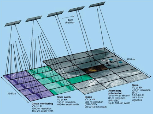
ASAR General Operation Strategy
ASAR offered, by exploiting the combinations of polarisations and incidence angles, 37 different and mutually exclusive operating modes in high-, medium- (wide swath mode), and reduced- (global monitoring mode) resolution. These modes were operated mainly in response to user requests. Wave mode was also mutually exclusive with respect to all the other modes. It was a low-rate mode operated systematically over oceans as part of the global mission. The global mission operation strategy was intended to provide the maximum coverage of the Earth components (atmosphere, ocean, ice, land) relevant to each payload instrument. This was based on:
- Continuous operation of the low-rate instruments around the orbit (with the exception of MERIS, which is limited by sun-illumination conditions)
- On-board recording of all instrument data
- Data-recorder playback at least once per orbit in order to ensure availability of fast delivery products within less than three hours from observation
- Systematic processing of all acquired data.
Global monitoring and wave modes were recorded systematically when operated. ASAR high- and medium-resolution imaging modes were either transmitted on a real time link (direct X-band or via ARTEMIS Ka-band link) or recorded on the on-board solid state recorder for ground data recovery. The high- and medium-resolution data were acquired only when required to satisfy either a background mission scenario and/or user requests.
ASAR Processing and Data Distribution
All ASAR high-rate data acquired by ESA facilities was systematically processed in near real time to generate medium-resolution products (around 150 m resolution) and browse products. Browse products were available on-line. High-resolution products were processed in near real time or off-line, upon user request. All medium- and high- resolution products were delivered to users on request either in near real time on a dissemination channel or off line on physical media.
MERIS General Operation Strategy
MERIS operated at full resolution (FR with 300 m resolution at nadir). The data was averaged on board to produce a separate data stream at reduced resolution (RR with 1200 m resolution at nadir). The two data streams were available in parallel on board. MERIS RR was systematically operated and recorded on board for the duration of the sun-illuminated segment.
MERIS FR was either transmitted on a real time link (direct X-band or via ARTEMIS Ka-band link) or recorded on the on-board solid state recorder for ground data recovery. The FR data was acquired only when required to satisfy either a background mission scenario and/or user requests. MERIS was nominally operated with a fixed set of bands. Alternative band sets were used for experiment campaigns of a few weeks duration.
MERIS Processing and Data Distribution
MERIS RR data acquired at ESA facilities was systematically processed in near real time to generate MERIS RR Level 1b and 2 products. Browse products were made available on-line.
Upon user request MERIS FR data was processed and distributed either in near real time (dissemination link) or off-line (physical media).
MERIS FR data browse images were systematically available since RR data were always acquired in parallel with FR data and browse products were systematically produced for all received RR data. Both RR and FR data were available for off-line processing and distribution. Near real time delivery of MERIS full-resolution products was also available.
Regional Mission Data Recovery
For operation and data recovery of ASAR high- and medium-resolution data and MERIS full resolution, the following nominal strategy was applied:
- Data over Europe was acquired directly via X-band links (Kiruna and Matera coverage)
- Data outside Europe was acquired whenever possible via ARTEMIS direct transmission to the UET located at ESRIN
- Data outside direct coverage of the ESA X-band stations and ARTEMIS, was recorded on board using the SSR and acquired via deferred dump to one of the ESA stations via X- or Ka-band links
- Data requested by a station operator or by the distributing entities on behalf of a station operator was transmitted in X-band for acquisition by the corresponding station
- If data was to be acquired by a station operator and was also needed as part of ESA archive, then in parallel with X-band direct data transmission, ESA acquired the data via combined use of the SSR, X- or Ka-links as appropriate.
In case of unavailability of ARTEMIS, whether temporary or permanent, the regional mission data acquisition was not affected. The time required to recover the data could restrict in some orbits the provision of three hour NRT services, but still preserved potential delivery of products to users within less than a day for data acquired over any site in the world.
Data Transmission
The satellite data transmission system allowed:
- Up to two X-band links operating at a time
- Up to two Ka-band links operating at a time
- X- and Ka-band transmitters operated independently, therefore up to two X-band links and two Ka-band links could be operated simultaneously.
ASAR HR operation, with real time data transmission, required use of one full RF channel at 100 Mbps. MERIS FR operation, with real time data transmission, required use of half an RF channel (50 Mbps). Therefore MERIS FR could share an RF channel with a simultaneous TR dump or an SSR dump at 50 Mbps. When there was no need for a full RF channel, the RF channel operated at half rate (50 Mbps) using BPSK modulation instead of the nominal 100 Mbps QPSK modulation.
The down link RF channel relaying the LR global data was be operated only when in visibility of ESA stations or ARTEMIS for dump of the recorded data. This measure needed to be taken to preserve satellite energy and lifetime of the corresponding on board transmitter.
Global Mission Scenario
The global mission operation included all Envisat instruments which had global coverage objectives and implied:
- Continuous operation of the low-rate instrument around the orbit (For MERIS, sun-illumination constraints limit the observation to about 43.5 minutes per orbit)
- On board recording of all instrument data
- Playback at least once per orbit to ensure availability of FD products within less than three hours from observation
- Systematic processing of all acquired data.
The global mission strategy was defined in the High Level Operation Plan (HLOP) approved by the programme participants. The corresponding detailed operation requirements for the FOS and PDS were defined in the Reference Operation Plan (ROP).
Regional Mission Scenario
- The ASAR high-rate operations in wide-swath mode and narrow-swath modes
- The MERIS full-resolution (FR) mode.
Data rates implied real time transmission or recording on SSR. Data acquisition was based on user requests plus a background operation scenario. The strategy for handling user requests was based on the Data Policy and the HLOP. The result was implemented via detailed ROP rules. Data processing to high resolution product was performed on user request.
Data recovery assumed combined use of:
- SSR
- ESA X-band stations
- Ka-band link via ARTEMIS
- X-band national and foreign stations having an agreement with ESA.
Simultaneous operation of Ka- and X-band channels was possible.
Envisat Mission Phases
Envisat had three main mission phases and an extension in 2010:
| Phase name | Phase Start | Phase Stop | Start Orbit | Stop Orbit | Repeat Cycle | Track Range | |
| 0 | LEOP (Launch & Early Orbit Phase) | 01/03/2002 02:53:55 | 02/03/2002 10:45:17 | 1 | 19 | _ | _ |
| 1 | Drift Phase | 02/03/2002 10:45:17 | 04/04/2002 00:37:34 | 20 | 485 | _ | _ |
| 2 | Nominal Phase | 04/04/2002 00:37:34 | 24/10/2010 07:05:25 | 486 | 45221 | 35 days | 1 - 501 |
| 3 | Mission Extension Phase | 24/10/2010 07:05:25 | 08/04/2012 12:06:32 | 45222 | 52867 | 30 days | 1 - 431 |
Mission Extension Phase
At the end of October 2010 a major change in the orbital parameters was performed to extend the Envisat mission.
The new orbital parameters allowed:
- To maintain the nominal mission until 2010
- To extend the mission beyond 2010
- To allow operations of all instruments with small or no degradation of their measurements, or minor impact on data quality.
The Envisat orbit change project, called 'Envisat 2010+', consisted in lowering the satellite from about 800 km to about 783 km on the morning of 22 October 2010.
The 8000 kg satellite was lowered by about 10 km with two 28-minute repositioning moves. Following another two manoeuvres on the evening of 26 October, the satellite was lowered an additional 7 km, reaching its new final altitude.
The End of Envisat Mission
After 10 years of service, exceeding its initially planned life span by five years and delivering over a petabyte of data, ESA announced they lost contact with Envisat on 8 April 2012. The spacecraft was still in a stable orbit, but it could not be contacted. Engineers spent a month attempting to regain contact with the satellite but Envisat did not respond to any commands.
The satellite had been operating with no signs of malfunction before 8 April, leading the engineers to wonder if the satellite had suffered external damage. The Pleiades satellite was used to acquire an image of Envisat, helping the team understand more about the spacecraft condition but not providing a definitive answer.
The possible failures included the loss of the power regulator, which would block telemetry and telecommands. Another possibility was a short circuit which may have trigged the satellite entering safe mode. Engineers also wondered if the satellite could have experienced another anomaly during a transition to safe mode, leaving Envisat in an intermediate and unknown condition.
ESA formally announced the end of Envisat's mission on 9 May 2012.
Read more about the end of the Envisat mission in this related news.