PRARE Overview
Applications
The high quality measurement of the ERS PRARE data as well as their good global repeatability, density, and spatial distribution suit the data for deriving several higher-level geodynamic products for such applications as:
- Precise satellite orbits
- Ground station coordinates
- Earth gravity field and Earth orientation parameters
- Ionospheric parameters
- Ultra-stable clock time information
The PRARE objective was precise satellite range determination leading to higher-accuracy altitude measurements. PRARE utilised 2.2 GHz and 8.5 GHz transmissions for ionospheric corrections and orbit determination, respectively. This information was needed for ocean circulation studies and geodetic applications such as sea-surface topography and crustal dynamics.
Design
PRARE was a microwave tracking system operating at centimetre accuracy levels for the measurement of satellite to ground range and range rate. The concept was based on an autonomous spaceborne two-way and dual frequency microwave tracking system with its own telemetry, telecommand, data storage, timing and data transmission capabilities. This allowed data analysis on a global basis within a very short time delay. Due to the microwave transmission concept, the system operated independently from weather and daylight conditions.
The PRARE system consisted of three major components:
- Space Segment: This was a small self-contained hardware unit with a mass of 19 kg, power consumption of 39 VA (operational), or 8 VA in standby mode, and communication links independent of the host satellite.
- Ground Station Network: The network consisted of small automated and transportable ground stations (whose positions were known or could be determined from PRARE data to high precision). At X-band a ground station worked as a regenerative and coherent transponder, at S-band a station acted as a receiver for the transmitted signals and measures the difference of the time of arrival of both signals.
- Control Segment consisting of:
- GFZ's Master Station located at DLR in Oberpfaffenhofen, Germany
- TimeTech's Monitoring and System Command Station in Stuttgart, Germany
- A Calibration Station in Potsdam, Germany
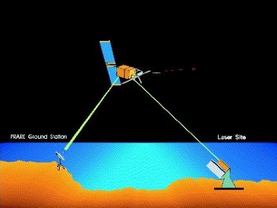
PRARE measurement principle:
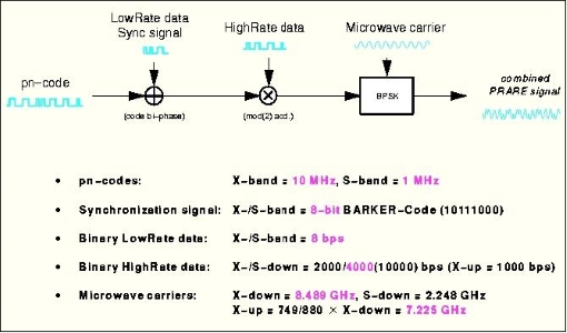
Two continuous signals were emitted from the space segment to the ground, one of which was in S-band (2.2 GHz), the other in X-band. Both signals were modulated with a PN-code (pseudo random noise, 1 MChirp/s for the S-band and 10 MChirp/s for the X-band) used for the distance measurement and containing data signals (broadcast information) for ground station operation (prediction of orbit visibility, etc.). The time delay in the reception of the two simultaneously emitted signals was measured at the ground stations with an accuracy of better than 1 ns; the result was retransmitted and stored in the on-board memory of PRARE for later ionospheric correction of the data.
In the ground station the received X-band signal was transposed to 7.2 GHz, coherently modulated with the regenerated PN code (or with one of three orthogonal copies for code multiplexing) and including the two-frequency delay data as well as housekeeping and meteorological ground data was retransmitted to the PRARE space segment.
These stations had special data evaluation, system control, and communication capabilities, which allowed to fully control the space segment on ERS-2 as well as each individual ground station via the primary PRARE microwave links. This unique feature made the PRARE system operations independent from the host satellite (except for power) and adaptable for any near-Earth communication, navigation, or observation satellite system.
PRARE system characteristics and measurement precision parameters
| X-band uplink | - 7225.296 MHz (carrier frequency) - PN-code = 10 Mbit/s, BPSK (bandwidth = 10 MHz) - Low rate data = 16 bit/s code-biphase modulation - High rate data = 1 kbit/s mod(2)-add. |
|---|---|
| Ground transponder power | 60 cm parabolic dish, 5 watts transmit |
| X-band downlink | - 8489 MHz (carrier frequency) - PN code =10 Mbit/s, BPSK (bandwidth = 10 MHz) - Low rate data = 16 bit/s code-biphase modulation - High rate data = 2/4/10 kbit/s mod(2)-add. |
| S-band downlink | - 248 MHz (carrier frequency) - PN-code = 1 Mbit/s, BPSK (bandwidth = 1 MHz) - Low rate data 16 bit/s code-biphase modulation - High rate data 2/4/10 kbit/s mod(2)-add. |
| Satellite antennas | Crossed dipoles at X-band and S-band, 1 W in downlink and 5 W in uplink transmission power |
| Noise values | ±1.5 cm rms for X-band ranging (1 measurement/s) ±0.05 mm/s rms for X-band Doppler (30 s integration time, 90º elevation) |
| Bias values | <1 cm for X-band; <3 cm for S-band (after post-processing) |
| Range-error estimation | Tropospheric error: 2-7 cm; ionospheric error <1 cm; Thermal noise and calibration error: 2-3 cm; Antenna phase center uncertainty <1 cm |
| Total ranging accuracy | 2.5-6.5 cm (root squared sum) |
| Total range-rate accuracy | 0.1 mm/s rms (root squared sum) |
Mission Operations
The ERS-1 PRARE instrument payload could not achieve operational status after launch. The instrument worked nominally for five days after launch (five contacts with the command station showed nominal telemetry). A thorough failure analysis came to the conclusion that the most likely cause of the PRARE failure was RAM damage due to radiation (destructive RAM latch-up).
The ERS-2 PRARE instrument was in "operational status" as of 1 January 1996 (i.e. the routine range and range rate product generation started on 1 January) providing measurement accuracies between 2.5 and 6.5 cm (two-way range data) and 0.1 mm/s (two-way range-rate data) respectively. PRARE operations were fully autonomous and separate from ERS-2 operations.
PRARE space segment:
The PRARE space segment consisted of a compact electronics box (dimensions 400 x 210 x 180 mm, power consumption 30W in operational mode and 8W in stand-by) and two crossed dipole antennas for transmission of the X-band and S-band signals. The X-band antenna also received the microwave signal after it had accomplished the round-trip transmission.
The space segment design featured four independent, parallel, strictly coherently operating receiver channels which track up to four PRARE ground stations that were in view of the satellite simultaneously. This allowed to generate overlapping measurement data used for internal calibration and for back-up of the main orbit solution. This required a very careful internal hardware design and sophisticated control of all modules.
The very heart of the whole PRARE system was the internal oscillator of the space segment which was not only responsible for time tagging of the signal generation and communication processes, but in fact controlled the complete system synchronisation in ultra-short- (up to 1 second), in short- (up to 1000 seconds) and in long-term (more than 1000 seconds):
- Control of the internal coherency of the space segment signals, both for range and range-rate measurement data as well as for inter-channel coherency.
- Time control of the whole ground station network by periodic synchronisation pulse generation and transmission.
The PRARE space segment oscillator was an ultra-stable voltage controlled quartz-crystal oscillator (VCXO) designed in BVA technique, and a state-of-the-art type of quartz oscillator. The primary output frequency is 5 MHz, which is divided/multiplied by the space segment electronics to generate all the frequencies necessary within the system.
The space segment was built by Kayser Threde of Munich, and TimeTech GmbH of Stuttgart; the ground stations were developed by Dornier GmbH, Friedrichshafen.
PRARE ground segment:

Dedicated ground stations were used, which were acting basically as regenerative transponders. A PRARE ground transponder consisted of:
- An antenna unit with an offset antenna of 60 cm diameter (parabolic dish), fronted electronics and tracking system. The antenna was fully movable in azimuth and elevation to track the satellite from horizon to horizon (weight 42 kg including gearing unit).
- An electronics unit including RF-modules (dimensions 560 x 560 x 300 mm, weight 35 kg), linked together by RF-signal and data cables. The electronic tracking loops filtered the received microwave signal, decoded the superimposed data (low-rate modulation), which contain dedicated information for each individual ground station, transposed the microwave frequency to the uplink (fixed frequency ratio 749/880), re-modulate new site-specific low-rate information, and sent the signal back to the satellite.
The PRARE ground station tracking network consisted of 29 PRARE transponders in total (globally distributed), which were owned by 10 different international geodetic research groups (plus GFZ) and operated locally by co-operating scientific institutions.
During satellite contact, the main tasks of the ground station modules were:
- X-band signal transponding
- Measurement of the delay difference between the quasi-simultaneously transmitted S- and X-band signals
- Measurement of the internal X-/X-signal path delay
- Meteorological data handling, acquired at the ground station site
- Clock pulse and time generation and synchronisation
- Low-rate and high-rate data reception and interpretation
- Low-rate data transmission
- Setup and calibration data interpretation and storage