Wind Scatterometer (WS) Overview
Applications
Wind scatterometers (WS) use accurate measurements of the radar backscatter from the ocean surface when illuminated by a microwave signal with a narrow spectral bandwidth to derive information on ocean surface wind velocity. At a given angle to the flight path of the satellite, the amount of backscatter depends on two factors - the size of the surface ripples of the ocean, and their orientation with respect to the propagation direction of the pulse of radiation transmitted by the scatterometer. The first is dependent on wind stress and hence wind speed at the surface, while the second is related to wind direction. Hence measurements by the ERS scatterometer may be used to derive both wind speed and direction.
Scatterometer instruments aim to achieve high accuracy measurements of wind vectors, and resolution is of secondary importance - the resolution of the ERS scatterometer was 50 km, though the grid sampling was 25 km. Because the scatterometer operated at microwave wavelengths, the measurements are available irrespective of weather conditions.
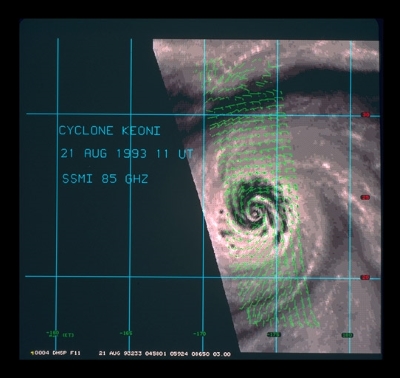
Information from the ERS wind scatterometer provided a unique source of data on sea surface wind speed and direction which has important applications in weather and wave forecasting and the investigation of climate models and elaboration. The assimilation of scatterometer data into atmospheric forecasting models greatly improved the description of cyclonic features so important in predicting future weather patterns.
There are numerous other applications, such as sea ice presence over the sea surface and soil moisture index over land surface.
Design
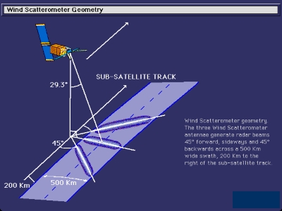
The ERS Wind Scatterometer was designed to obtain information on wind speed and wind direction over sea surfaces. Therefore it is often called Wind Scatterometer. It used three sideways-looking antennae to the right with respect to satellite track: one looking forward at 45 degrees (fore-beam) in the direction of the satellite flight path, another one sideways (mid-beam), and one facing 45 degrees in the rear direction with respect to the satellite's flight direction. The antenna radar beams illuminated a swath 500 km wide as the satellite advanced along its orbit and each provided measurements of radar backscatter from the sea surface for overlapping 50 km resolution cells using 25 km grid-spacing.
The result was three independent backscatter measurements relating to cell centre nodes on a 25 km grid, which were obtained using the three different viewing directions and were separated by only a very short time delay. Thus three backscatter measurements of each grid point were obtained at different viewing angles and separated by a short time delay. These "triplets" were fed to a mathematical model which calculates the surface windspeed direction, or used directly over ice and land.
Measurement Sequence
A transmit pulse was produced by the Scatterometer Electronics and amplified by the IF Radar unit, converted to an RF signal in the transmitter/converter unit and amplified by the High-Power Amplifier. The transmit signal was routed to the correct antenna by the Circulator Assembly which in this mode is under the control of the Scatterometer Electronics.
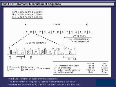
The received signal was down-converted, amplified by the IF Radar and routed to the Scatterometer Electronics. A measurement sequence of 3.763 seconds corresponds to 25 km along the sub-satellite track at a satellite altitude of 785 km and was continuously repeated in the wind mode without any gap. This sequence involved four sets of measurements, regularly spaced, for each antenna beam (fore, mid and aft). Each series corresponded to 32 measurement pulses on each beam. Noise measurements and internal calibration were regularly performed in the interval between the transmitted pulse and the reception of the return echo.
For the mid-beam, the return echo was filtered and sampled in complex form I and Q, while for the fore and aft-beams, as the Doppler variation is significant over the swath width (20 KHz near swath to 140 KHz far swath), a programmable Doppler compensation law was applied to the received signal before filtering and complex sampling.
The main technical characteristics of the Wind Scatterometer:
| Time Period | 21 April 1995 – 5 July 2011 |
|---|---|
| Frequency | 5.3 GHz ± 52 kHz (C band) |
| Antenna Azimuth Orientations | Three fixed |
| Polarizations | Linear vertical (VV) |
| Beam Resolution | Range Gate |
| Resolution | 25/50 km |
| Number of pulses per 50 km | 256 |
| Swath width | 500 km |
| Incidence Angle | 18 – 59o |
| Orbit | Sun-synchronous |
| 780 km altitude | |
| 98.52° inclination |
Sensor Modes
The European Remote Sensing Satellites (ERS) carried an Active Microwave Instrument (AMI), which combined the functions of a Synthetic Aperture Radar (SAR) and a Scatterometer.
The AMI provided radar backscattering coefficient measurements by using its three nominal operational acquisition modes: Synthetic Aperture mode (SAR mode - green), Scatterometer mode (wind mode - brown) and a special combination of the two over ocean where SAR and Scatterometer mode were interleaved (wind/wave mode - blue).
The wind/wave mode consisted of the Scatterometer operation interrupted every 30 seconds by a couple of seconds of short SAR operation in order to acquire small SAR imagettes.