RA (ERS) Overview
Applications
The ERS Radar Altimeter (RA) operated in two modes: ocean mode and ice mode. The RA operated by timing the two-way delay for a short duration radio frequency pulse, transmitted vertically downwards. The required level of range measurement accuracy (better than 10 cm) calls for a pulse compression technique (chirp). The instrument employed frequency modulation and spectrum analysis of the pulse shape.
In ocean mode a chirped pulse of 20 micro-s duration was generated with a band width of 330 MHz. For tracking in ice mode an increased dynamic range is used, obtained by reducing the chirp bandwidth by a factor of four to 82.5 MHz, though resulting in a coarser resolution.
The Radar Altimeter for ERS-1 and ERS-2 was designed to meet very demanding constraints and had the following major objectives:
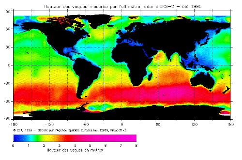
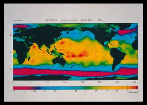
- Precise altitude (ocean surface elevation for the study of ocean currents, the tides and the global geoid) - global measurements of the height of the ocean waves (as significant wave height) - such measurements are extremely important to marine users and scientists wishing to understand the ocean's dynamic behaviour. The Radar Altimeter provided measurements to latitude 82°, north and south, extending to regions which previously had no regular observations - this included the major wave-generation regions in the Southern oceans.
- Significant wave height (SWH) - measurements of the satellite's height above the local mean sea surface, with an unprecedented precision (equivalent to 1 cm in 100 km) - the applications of this dataset are numerous, for example the operational monitoring of the boundaries of major ocean currents, likely to have significant economic benefits.
- Ocean surface wind speed - global measurements of wind speed - these can be used to complement the SAR and Scatterometer wind field measurements and also combined with the Radar Altimeter measurements of SWH to distinguish swell from wind-driven waves.
- Various ice parameters (surface topography, ice types, sea/ice boundaries) - the ability to make measurements over ice with the long term monitoring of the topography of the ice sheets providing a vital warning capability for any substantial shift in the world's climate.
Design
The Radar Altimeter antenna consisted of a reflector, waveguide feed, tripod plus supporting structure, horn feed and the waveguide. In ocean mode a chirped pulse of 20 micro-s duration was generated with a band width of 330 MHz. For tracking in ice mode an increased dynamic range is used, obtained by reducing the chirp bandwidth by a factor of four to 82.5 MHz, though resulting in a coarser resolution.
The Frequency Generator units provided the transmit signal at a frequency of 450 MHz to the chirp generator. This generated a chirped output with a bandwidth of 165 MHz (ocean) and 41.25 MHz (ice), gated within a pulse of 20 micro-s. This signal was up-converted and multiplied (using C- and L-band LO signals) to 13.8 GHz, with 330 MHz (ocean) and 82.5 MHz (ice) bandwidths. The required power output level (42 dBm) was generated by the High Power Amplifier (HPA), which was realised as a Travelling Wave Tube and Electronic Power Conditioner (TWT/EPC) combination. A harmonic filter at the TWT output attenuated the harmonics of the RF signal. The transmitter signal was fed to the antenna.
The returned signal was routed to the receiver via the Front End Electronics, with an insertion loss of approximately 1.6 dB. The received chirp signal was deramped by mixing it with the LO chirp at a frequency of 15.025 GHz. The deramped output (first IF) was at 1.225 GHz. The signal was then amplified to recover the conversion loss, filtered and mixed with a second LO chirp (1.3 GHz) to provide a second IF of 75 MHz. The second IF signal was filtered, using a surface acoustic wave (SAW) device with a bandwidth of 3.2 MHz and passed via a step attenuator. This provided an overall gain adjustment over a 62 dB range, implemented as two 31 dB step attentuators with a step size of 1 dB. The output was then coherently detected by a quadrature IF mixer to obtain the I- and Q-components of the received signal.
The Processor and Data Handling Sub-system (PDHSS) performed tracking and the necessary processing of the radar echoes in order to maintain the echo within the radar range-window.
Measurements over ocean
The return pulse shape as a function of time is the convolution of three functions:
- the average flat surface impulse response, which is a function incorporating the antenna beam weighting and the geometric spreading of the radar pulse along the original surface
- the probability distribution of surface heights over the sea surface, expressed in terms of delay times
- the altimeter system point-target response, which is a function of pulse width
Over ocean surfaces, the distribution of the heights of reflecting facets is gaussian or near-gaussian, and the echo waveform has a characteristic shape that can be described analytically, as a function of the standard deviation of the distribution which is closely related to the ocean wave height.
The resulting return pulse shape is shown in the figure. In general terms the ocean mode encompassed the following echo characteristics:
- time delay with respect to the transmitted pulse - this provides the measure of altitude;
- slope of the echo leading edge, which is related to the width of the height distribution of reflecting facets, and thus to wave height parameters such as SWH;
- the power level of the echo signal, which depends on small scale surface roughness, and thus on surface wind-field parameters over the ocean.
Real echoes are composed of the sums of signals from many point scatterers, each with individual phase and amplitude. Therefore, the individual echoes have statistical characteristics superimposed on the pulse shape. In order to reduce uncertainties in the determination of pulse characteristics, the altimeter averages pulses together to reduce this statistical effect. When in ocean tracking mode, the mean sea-level point (mid point of the leading edge) on the time axis is maintained in the centre of the range window. The time interval between the transmitted pulse and this point is effectively the classical radar measurement of range.
Measurements over ice
From other surfaces the waveform shape does not always conform to the simple Brown Model. The return echo from sea ice appears more specular than that from the ocean and has a peaked trace. The variability of the range measurement is of the same order as that from the ocean and this surface can therefore be tracked using the altimeter ocean tracking mode. The situation is different for continental ice, as the typical return echo has unpredictable shape and more importantly can have a larger variability in surface elevation
An altimeter waveform over continental ice where the typical return echo has unpredictable shape and can have a larger variability in surface elevation.
In order to maintain track of the surface, the Radar Altimeter, in ice mode, benefited from a wider observation window. The required increase in the size of the observation window was obtained by reducing the pulse bandwidth by a factor of four. This solution did not change the intermediate frequency (IF) bandwidth and was equivalent to enlarging the filter bandwidth without changing the filter bank; therefore it did not introduce major hardware changes into the system. In ice mode, tracking the echo of unpredictable shape was achieved by tracking the centre of gravity of the return pulse rather than the leading edge. This technique was used as the location of the centre of gravity is always unique, whereas there may be more than one leading edge, so avoiding any ambiguities.
The main instrument parameters and technical characteristics of the Radar Altimeter
- Mass: <= 96 kg
- Antenna diameter: 1.2 m
- DC power: <=134.5 W
- Data rate: <= 15 kbit/sec
- Bandwidth:
- ocean mode: 330 MHz
- ice mode: 82.5 MHz
- Pulse repetition frequency: 1020 Hz
- RF transmit power: 50 W
- Pulse length: 20 micro-s chirp
- Altitude measurement: 10 cm (1s, SWH = 16 m)
- Significant wave height: 0.5 m or 10% (1s) whichever is smaller
- Backscatter coefficient: 0.7 dB (1s)
- Echo waveform samples: 64 x 16 bits at 20 Hz
- Beam width: 1.3°
- Sea surface elevation: better than 10 cm
- Spatial Resolution: Footprint is 16 km - 20 km, depending on sea state
- Waveband: Microwave: Ku-band: 13.8GHz
Sensor Modes
The ERS Radar Altimeter operated in 2 modes: ocean mode and ice mode. Beam width = 1.3° foot print = 16 - 20 m (depending on sea state). RA-1 operated by timing the two-way delay for a short duration radio frequency pulse, transmitted vertically downwards. The required level of range measurement accuracy (better than 10 cm) calls for a pulse compression technique (chirp). The instrument employs frequency modulation and spectrum analysis of the pulse shape. RA-1 provided measurements leading to the determination of:
- Precise altitude (ocean surface elevation for the study of ocean currents, the tides and the global geoid)
- Significant wave height
- Ocean surface wind speed
- Various ice parameters (surface topography, ice types, sea/ice boundaries)
More details about RA (ERS-2) Sensor Modes are available in an ESA Bulletin
Instrument Operations
Find out about RA (ERS-2) instrument operations