- All Categories (137)
- Data (57)
- News (30)
- Missions (3)
- Events (25)
- Tools (2)
- Activities (6)
- Campaigns (6)
- Documents (8)
DATA
Discover and download the Earth observation data you need from the broad catalogue of missions the European Space Agency operate and support.
Data - Sample Data (Open)
IRS-P6 (ResourceSat-1) Sample Data
Download free IRS-P6 (ResourceSat-1) sample datasets to preview products available for this mission.
Data - Announcement of Opportunity (Restrained)
Announcement of Opportunity for NovaSAR-1
ESA is launching an Announcement of Opportunity for the international scientific community to access data from the NovaSAR-1 mission for science and EO-based applications development.
Data - Project Proposal (Restrained)
NovaSAR-1 new tasking
NovaSAR-1 new acquisition data are available in two baseline acquisition modes: Stripmap – provides the highest resolution of 6 metres with up to 20 km swath selected from a 150 km field of regard, available in single polarisation. ScanSAR – has a 20 - 30 metre resolution and up to 150 km swath. Available in single polarisation. Within each of the baseline modes there are a variety of mode options that vary according to ground range resolution, incidence angles, swath width and the number of looks: Acquisition Mode Polarisation Resolution (m) Swath Width (km) Incidence Angles Number of Looks Stripmap Single: HH 6 20 16.0 – 25.38° 3 (1 range, 3 azimuth) 13 – 20 21.29 – 31.2° Single: VV 6 20 16.0 – 25.38° 3 (1 range, 3 azimuth) 13 – 20 21.29 – 31.2° ScanSAR Single: HH 20 100 15.0 - 24.66° 4 (2 range, 2 azimuth) 50 24.51 - 28.94° Single: VV 20 100 15.0 – 24.66° 4 (2 range, 2 azimuth) 50 24.51 - 28.94° Single: HH 30 150 11.29 – 25.93° 4 (2 range, 2 azimuth) 55 27.35 - 32.01° Single: VV 30 150 11.29 – 25.93° 4 (2 range, 2 azimuth) 55 27.35 - 32.01° NovaSAR-1 data are provided as a Level 2 (ARD) product as standard, but the accompanying Level 1 data may also be requested. Level 1 – delivered as reconstructed, unprocessed instrument data at full resolution. Level 2 (ARD) – delivered as a processed product with applied radiometric and geometric corrections i.e. orthorectification and spatial registration: Geocoded Ellipsoid Corrected (GEC) – Maritime and ocean applications Geocoded Terrain Corrected (GTC) – Land applications and change detection Where available, associated automatic identification system (AIS) data may be requested alongside the NovaSAR-1 data products.
Data - Fast Registration with immediate access (Open)
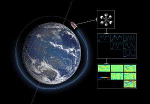
FSSCat products
The FSSCat collection provides hyperspectral data coverage over a number of locations around the world, as measured by the HyperScout 2 sensor. The FSSCat hyperspectral data products are comprised of 50 spectral bands, covering a spectral range of 450 – 950 nm with a spectral resolution of 18 nm (at FWHM). Imagery is available with an along-track ground sampling distance (GSD) of 75 m. To ensure a high degree of radiometric accuracy, HyperScout 2 data are validated through comparison with Sentinel-2 data products. The processing level of the data is L1C – calibrated top-of-atmosphere radiance, reflectance or brightness temperature. The raster type of the L1C data product is a GRID – a 2D or 3D raster where the (geo)location of the data is uniquely defined by the upper left pixel location of the raster and the pixel size of the raster, and the projection parameters of the raster (if georeferenced). The third dimension can e.g. be a spectral or third spatial dimension. The L-1C VNIR data product includes a hyperspectral cube of TOA reflectance in the VNIR range, as well as relevant meta-data that adheres to EDAP's best practice guidelines. This product consists of georeferenced and ortho-rectified image tiles that contain spectral reflectance data at the top-of-the-atmosphere. Each image tile contains radiometrically corrected and ortho-rectified band images that are projected onto a map, as well as geolocation information and the coordinate system used. Additionally, each image pixel provides TOA spectral reflectance data in scaled integers, conversion coefficients for spectral radiance units, viewing and solar zenith and azimuth angles, and quality flags.
Data - Fast Registration with approval (Restrained)
European Cities: Cartosat-1 Euro-Maps 3D
A large number of European cities are covered by this dataset; for each city you can find one or more Cartosat-1 ortho image products and one or more Euro-Maps 3D DSM tiles clipped to the extent of the ortho coverage. The Euro-Maps 3D DSM is a homogeneous, 5 m spaced Digital Surface Model semi-automatically derived from 2.5 m Cartosat-1 in-flight stereo data with a vertical accuracy of 10 m. The very detailed and accurate representation of the surface is achieved by using a sophisticated and well adapted algorithm implemented on the basis of the Semi-Global Matching approach. The final product includes several pixel-based quality and traceability layers: The dsm layer (*_dsm.tif) contains the elevation heights as a geocoded raster file The source layer (*_src.tif) contains information about the data source for each height value/pixel The number layer (*_num.tif) contains for each height value/pixel the number of IRS-P5 Cartosat-1 stereo pairs used for the generation of the DEM The quality layer (*_qc.tif) is set to 1 for each height/pixel value derived from IRS-P5 Cartosat-1 data and which meets or exceeds the product specifications The accuracy vertical layer (*_acv.tif) contains the absolute vertical accuracy for each quality controlled height value/pixel. The ortho image is a Panchromatic image at 2.5 m resolution. The following table defines the offered product types. EO-SIP product type Description PAN_PAM_3O IRS-P5 Cartosat-1 ortho image DSM_DEM_3D IRS-P5 Cartosat-1 DSM
Data - EO Sign In Authentication (Open)
PAZ ESA archive
The PAZ ESA archive collection consists of PAZ Level 1 data previously requested by ESA supported projects over their areas of interest around the world and, as a consequence, the products are scattered and dispersed worldwide and in different time windows. The dataset regularly grows as ESA collects new products over the years. Available modes are: StripMap mode (SM): SSD less than 3 m for a scene 30 km x 50 km in single polarization or 15 km x 50 km in dual polarisation ScanSAR mode (SC): the scene is 100 x 150 km2, SSD less than 18 m in signle pol only Wide ScanSAR mode (WS): single polarisation only, with SS less than 40 m and scene size of 270 x 200 km2 Spotlight modes (SL): SSD less than 2 m for a scene 10 km x 10 km, both single and dual polarization are available High Resolution Spotlight mode (HS): in both single and dual polarisation, the scene is 10x5 km2, SSD less than 1 m Staring Spotlight mode (ST): SSD is 25 cm, the scene size is 4 x 4 km2, in single polarisation only. The available geometric projections are: Single Look Slant Range Complex (SSC): single look product, no geocoding, no radiometric artifact included, the pixel spacing is equidistant in azimuth and in ground range Multi Look Ground Range Detected (MGD): detected multi look product, simple polynomial slant-to-ground projection is performed in range, no image rotation to a map coordinate system is performed Geocoded Ellipsoid Corrected (GEC): multi look detected product, projected and re-sampled to the WGS84 reference ellipsoid with no terrain corrections Enhanced Ellipsoid Corrected (EEC): multi look detected product, projected and re-sampled to the WGS84 reference ellipsoid, the image distortions caused by varying terrain height are corrected using a DEM. The following table summarises the offered product types. EO-SIP product type Operation Mode Geometric Projection Geometric Projection PSP_SM_SSC Stripmap (SM) Single Look Slant Range Complex (SSC) PSP_SM_MGD Stripmap (SM) Multi Look Ground Range Detected (MGD) PSP_SM_GEC Stripmap (SM) Geocoded Ellipsoid Corrected (GEC) PSP_SM_EEC Stripmap (SM) Enhanced Ellipsoid Corrected (EEC) PSP_SC_MGD ScanSAR (SC) Multi Look Ground Range Detected (MGD) PSP_SC_GEC ScanSAR (SC) Multi Look Ground Range Detected (MGD) PSP_SC_EEC ScanSAR (SC) Geocoded Ellipsoid Corrected (GEC) PSP_SC_SSC ScanSAR (SC) Enhanced Ellipsoid Corrected (EEC) PSP_SL_SSC Spotlight (SL) Single Look Slant Range Complex (SSC) PSP_SL_MGD Spotlight (SL) Multi Look Ground Range Detected (MGD) PSP_SL_GEC Spotlight (SL) Geocoded Ellipsoid Corrected (GEC) PSP_SL_EEC Spotlight (SL) Enhanced Ellipsoid Corrected (EEC) PSP_HS_SSC High Resolution Spotlight (HS) Single Look Slant Range Complex (SSC) PSP_HS_MGD High Resolution Spotlight (HS) Multi Look Ground Range Detected (MGD) PSP_HS_GEC High Resolution Spotlight (HS) Geocoded Ellipsoid Corrected (GEC) PSP_HS_EEC High Resolution Spotlight (HS) Enhanced Ellipsoid Corrected (EEC) PSP_ST_SSC Staring Spotlight (ST) Single Look Slant Range Complex (SSC) PSP_ST_MGD Staring Spotlight (ST) Multi Look Ground Range Detected (MGD) PSP_ST_GEC Staring Spotlight (ST) Geocoded Ellipsoid Corrected (GEC) PSP_ST_EEC Staring Spotlight (ST) Enhanced Ellipsoid Corrected (EEC) PSP_WS_SSC Wide ScanSAR (WS) Single Look Slant Range Complex (SSC) PSP_WS_MGD Wide ScanSAR (WS) Multi Look Ground Range Detected (MGD) PSP_WS_GEC Wide ScanSAR (WS) Geocoded Ellipsoid Corrected (GEC) PSP_WS_EEC Wide ScanSAR (WS) Enhanced Ellipsoid Corrected (EEC) As per ESA policy, very high-resolution data over conflict areas cannot be provided.
Data - External Data (Restrained)
Odin OSIRIS data products
The Odin OSIRIS (Optical Spectrograph and Infra-Red Imaging System) data provides vertical profiles measures of spectrally dispersed, limb scattered sunlight from the upper troposphere into the lower mesosphere. The data products are regularly processed and provide Ozone density vertical profiles (both Level 2 and Level 3), vertical profiles of stratospheric Aerosol (both Level 2 and Level 3), slant column densities of nitrogen dioxide NO2 profiles (Level 2), stratospheric BrO profiles (Level 2).
Data - Project Proposal (Restrained)
SPOT-6 to 7 full archive and tasking
The SPOT 6 and 7 satellites ensure data continuity with the no longer operational SPOT 5 satellite and provide an archive of very high resolution optical acquisition as well as the possibility to task the satellites for new acquisitions. Following the completion of the SPOT 7 mission in March 2023, new acquisition tasking is only available for the SPOT 6 satellite. The ortho-products are automatically generated by the SPOT 6 and 7 ground segment, based on SRTM database or Reference3D when available. The projection available for SPOT 6 and 7 ortho-products is UTM, datum WGS84. Bands combinations: Pansharpened: colour image at 1.5 m resolution Bundle: 1.5 m panchromatic image and 6 m multispectral image. Geometric processing levels: Primary: The Primary product is the processing level closest to the natural image acquired by the sensor. This product restores perfect collection conditions: the sensor is placed in rectilinear geometry, and the image is clear of all radiometric distortion. Standard Ortho: The Ortho product is a georeferenced image in Earth geometry, corrected from acquisition and terrain off-nadir effects. Tailored ortho: Aside from the Standard Ortho product, when different specifications are needed, a custom orthorectification, with a more precise 3D model provided by the client or acquired for the purpose, can be provided on demand. As per ESA policy, very high-resolution imagery of conflict areas cannot be provided.
Data - Data Description
Envisat ASAR AP Co- and Cross-polar L0 [ASA_APC/APH/APV_0P]
The ASAR Alternating Polarization Mode Level 0 (Co-polar and Cross-polar H and V) products contain time-ordered Annotated Instrument Source Packets (AISPs) corresponding to one of the three possible polarisation combinations: HH & HV, VV & VH and HH & VV, respectively. The echo samples in the AISPs have been compressed to 4 bits/sample using FBAQ. This is a high-rate, narrow swath mode, so data is only acquired for partial orbit segments. There are two co-registered images per acquisition and may be from one of seven different image swaths. The Level 0 product was produced systematically for all data acquired within this mode. Data Size: 56-100 km across track x 100 km along track. There are three AP Mode Level 0 products: ASA_APH_0P: The Cross-polar H Level 0 product corresponds to the polarisation combination HH/HV. ASA_APV_0P: The Cross-polar V Level 0 product corresponds to the polarisation combination VV/VH. ASA_APC_0P: The Co-polar Level 0 product corresponds to the polarisation combination HH/VV= H and H received/V transmit and V received.
Data - Fast Registration with approval (Restrained)
ALOS PRISM L1B
This collection provides access to the ALOS-1 PRISM (Panchromatic Remote-sensing Instrument for Stereo Mapping) L1b data acquired by ESA stations in the ADEN zone, in addition to worldwide data requested by European scientists. The ADEN zone was the area belonging to the European Data node and covered both the European and African continents, a large part of Greenland and the Middle East. The full mission archive is included in this collection, though with gaps in spatial coverage outside of the ADEN zone. The full mission is covered, though with gaps outside of the ADEN zone: Time window: from 2006-07-09 to 2011-03-31 Orbits: from 2425 to 24189 Path (corresponds to JAXA track number): from 1 to 668 Row (corresponds to JAXA scene centre frame number): from 55 to 7185. Two different Level 1B product types (Panchromatic images in VIS-NIR bands, 2.5 m resolution at nadir) are offered, one for each available sensor mode: PSM_OB1_11 -> Composed of up to three views; Nadir, Forward and Backward at 35 km swath PSM_OB2_11 -> Composed of up to two views; Nadir view at 70 km width and Backward view at 35 km width. All ALOS PRISM EO-SIP products have, at least, the Nadir view which is used for the frame number identification. All views are packaged together; each view, in CEOS format, is stored in a directory named according to the view ID according to the JAXA naming convention.
Data - Fast Registration with approval (Restrained)
RADARSAT-2 ESA archive
The RADARSAT-2 ESA archive collection consists of RADARSAT-2 products requested by ESA supported projects over their areas of interest around the world. The dataset regularly grows as ESA collects new products over the years. Following Beam modes are available: Standard, Wide Swath, Fine Resolution, Extended Low Incidence, Extended High Incidence, ScanSAR Narrow and ScanSAR Wide. Standard Beam Mode allows imaging over a wide range of incidence angles with a set of image quality characteristics which provides a balance between fine resolution and wide coverage, and between spatial and radiometric resolutions. Standard Beam Mode operates with any one of eight beams, referred to as S1 to S8, in single and dual polarisation . The nominal incidence angle range covered by the full set of beams is 20 degrees (at the inner edge of S1) to 52 degrees (at the outer edge of S8). Each individual beam covers a nominal ground swath of 100 km within the total standard beam accessibility swath of more than 500 km. Beam Mode Product Nominal Resolution (metres) Nominal Pixel Spacing Range x Azimuth (metres) Resolution Range x Azimuth (metres) Nominal Scene Size Range x Azimuth (kilometres) Range of Angle of Incidence (degrees) Number of Looks Range x Azimuth Polarisations Options Standard SLC 25 8.0 or 11.8 x 5.1 9.0 or 13.5 x 7.7 100 x 100 20 - 52 1 x 1 Single Pol HH or VV or HV or VH - or - Dual HH + HV or VV + VH SGX 8.0 x 8.0 26.8 - 17.3 x 24.7 1 x 4 SGF 12.5 x 12.5 SSG, SPG Wide Swath Beam Mode allows imaging of wider swaths than Standard Beam Mode, but at the expense of slightly coarser spatial resolution. The three Wide Swath beams, W1, W2 and W3, provide coverage of swaths of approximately 170 km, 150 km and 130 km in width respectively, and collectively span a total incidence angle range from 20 degrees to 45 degrees. Polarisation can be single and dual. Beam Mode Product Nominal Resolution (metres) Nominal Pixel Spacing Range x Azimuth (metres) Resolution Range x Azimuth (metres) Nominal Scene Size Range x Azimuth (kilometres) Range of Angle of Incidence (degrees) Number of Looks Range x Azimuth Polarisations Options Wide SLC 30 11.8 x 5.1 13.5 x 7.7 150 x 150 20 - 45 1 x 1 Single: Pol HH or VV or HV or VH - or - Dual: HH + HV or VV + VH SGX 10 x 10 40.0 - 19.2 x 24.7 1 x 4 SGF 12.5 x 12.5 SSG, SPG Fine Resolution Beam Mode is intended for applications which require finer spatial resolution. Products from this beam mode have a nominal ground swath of 50 km. Nine Fine Resolution physical beams, F23 to F21, and F1 to F6 are available to cover the incidence angle range from 30 to 50 degrees. For each of these beams, the swath can optionally be centred with respect to the physical beam or it can be shifted slightly to the near or far range side. Thanks to these additional swath positioning choices, overlaps of more than 50% are provided between adjacent swaths. RADARSAT-2 can operate in single and dual polarisation for this beam mode. Beam Mode Product Nominal resolution (metres) Nominal Pixel Spacing Range x Azimuth (metres) Resolution Range x Azimuth (metres) Nominal Scene Size Range x Azimuth (kilometres) Range of Angle of Incidence (degrees) Number of Looks Range x Azimuth Polarisations Options Fine SLC 8 4.7 x 5.1 5.2 x 7.7 50 x 50 30 - 50 1 x 1 Single: Pol HH or VV or HV or VH - or - Dual: HH + HV or VV + VH SGX 3.13 x 3.13 10.4 - 6.8 x 7.7 1 x 1 SGF 6.25 x 6.25 SSG, SPG In the Extended Low Incidence Beam Mode, a single Extended Low Incidence Beam, EL1, is provided for imaging in the incidence angle range from 10 to 23 degrees with a nominal ground swath coverage of 170 km. Some minor degradation of image quality can be expected due to operation of the antenna beyond its optimum scan angle range. Only single polarisation is available. Beam Mode Product Nominal resolution (metres) Nominal Pixel Spacing Range x Azimuth (metres) Resolution Range x Azimuth (metres) Nominal Scene Size Range x Azimuth (kilometres) Range of Angle of Incidence (degrees) Number of Looks Range x Azimuth Polarisations Options Extended Low SLC 25 8.0 x 5.1 9.0 x 7.7 170 x 170 10 - 23 1 x 1 Single: HH SGX 10.0 x 10.0 52.7 - 23.3 x 24.7 1 x 4 SGF 12.5 x 12.5 SSG, SPG In the Extended High Incidence Beam Mode, six Extended High Incidence Beams, EH1 to EH6, are available for imaging in the 49 to 60 degree incidence angle range. Since these beams operate outside the optimum scan angle range of the SAR antenna, some degradation of image quality, becoming progressively more severe with increasing incidence angle, can be expected when compared with the Standard Beams. Swath widths are restricted to a nominal 80 km for the inner three beams, and 70 km for the outer beams. Only single polarisation available. Beam Mode Product Nominal resolution (metres) Nominal Pixel Spacing Range x Azimuth (metres) Resolution Range x Azimuth (metres) Nominal Scene Size Range x Azimuth (kilometres) Range of Angle of Incidence (degrees) Number of Looks Range x Azimuth Polarisations Options Extended High SLC 25 11.8 x 5.1 13.5 x 7.7 75 x 75 49 - 60 1 x 1 Single Pol HH SGX 8.0 x 8.0 18.2 - 15.9 x 24.7 1 x 4 SGF 12.5 x 12.5 SSG, SPG ScanSAR Narrow Beam Mode provides coverage of a ground swath approximately double the width of the Wide Swath Beam Mode swaths. Two swath positions with different combinations of physical beams can be used: SCNA, which uses physical beams W1 and W2, and SCNB, which uses physical beams W2, S5, and S6. Both options provide coverage of swath widths of about 300 km. The SCNA combination provides coverage over the incidence angle range from 20 to 39 degrees. The SCNB combination provides coverage over the incidence angle range 31 to 47 degrees. RADARSAT-2 can operate in single and dual polarisation for this beam mode. Beam Mode Product Nominal resolution (metres) Nominal Pixel Spacing Range x Azimuth (metres) Resolution Range x Azimuth (metres) Nominal Scene Size Range x Azimuth (kilometres) Range of Angle of Incidence (degrees) Number of Looks Range x Azimuth Polarisations Options ScanSAR Narrow SCN, SCF, SCS 20 25 x 25 81 - 38 x 40 - 70 300 x 300 20 - 46 2 x 2 Single Co or Cross: HH or VV or HV or VH - or - Dual: HH + HV or VV + VH ScanSAR Wide Beam Mode provides coverage of a ground swath approximately triple the width of the Wide Swath Beam Mode swaths. Two swath positions with different combinations of physical beams can be used: SCWA, which uses physical beams W1, W2, W3, and S7, and SCWB, which uses physical beams W1, W2, S5 and S6. The SCWA combination allows imaging of a swath of more than 500 km covering an incidence angle range of 20 to 49 degrees. The SCWB combination allows imaging of a swath of more than 450 km covering the incidence angle. Polarisation can be single and dual. Beam Mode Product Nominal resolution (metres) Nominal Pixel Spacing Range x Azimuth (metres) Resolution Range x Azimuth (metres) Nominal Scene Size Range x Azimuth (kilometres) Range of Angle of Incidence (degrees) Number of Looks Range x Azimuth Polarisations Options ScanSAR Wide SCW, SCF, SCS 100 50 x 50 163 - 73 x 78 - 106 500 x 500 20 - 49 4 x 2 Single Co or Cross: HH or VV or HV or VH - or - Dual: HH + HV or VV + VH These are the different products : SLC (Single Look Complex): Amplitude and phase information is preserved. Data is in slant range. Georeferenced and aligned with the satellite track SGF (Path Image): Data is converted to ground range and may be multi-look processed. Scene is oriented in direction of orbit path. Georeferenced and aligned with the satellite track. SGX (Path Image Plus): Same as SGF except processed with refined pixel spacing as needed to fully encompass the image data bandwidths. Georeferenced and aligned with the satellite track SSG(Map Image): Image is geocorrected to a map projection. SPG (Precision Map Image): Image is geocorrected to a map projection. Ground control points (GCP) are used to improve positional accuracy. SCN(ScanSAR Narrow)/SCF(ScanSAR Wide) : ScanSAR Narrow/Wide beam mode product with original processing options and metadata fields (for backwards compatibility only). Georeferenced and aligned with the satellite track SCF (ScanSAR Fine): ScanSAR product equivalent to SGF with additional processing options and metadata fields. Georeferenced and aligned with the satellite track SCS(ScanSAR Sampled) : Same as SCF except with finer sampling. Georeferenced and aligned with the satellite track. Spatial coverage: Check the spatial coverage of the collection on a map available on the Third Party Missions Dissemination Service.
Data - Announcement of Opportunity (Restrained)
Announcement of Opportunity for NoR
ESA invites submissions for the Network of Resources (NoR) call, which aims to support research, development and pre-commercial users to innovate their working practices, moving from a data download paradigm towards a 'bring the user to the data' paradigm.
Data - Project Proposal (Restrained)
PAZ Full Archive and New Tasking
PAZ Image Products can be acquired in eight image modes with flexible resolutions (from 1 m to 40 m) and scene sizes. Thanks to different polarimetric combinations and processing levels the delivered imagery can be tailored specifically to meet the requirements of the application. Available modes are: StripMap mode (SM): in single and dual polarisation: The ground swath is illuminated with a continuous train of pulses while the antenna beam is pointed to a fixed angle, both in elevation and in azimuth. ScanSAR mode (SC): in single polarisation: the swath width is increased in respect to the StripMap mode, it is composed of four different sub-swaths, which are obtained by antenna steering in elevation direction Wide ScanSAR mode (WS), in single polarisation: the usage of six sub-swaths allows to obtain a higher swath coverage product Spotlight modes: in single and dual polarisation: Spotlight modes take advantage of the beam steering capability in the azimuth plane to illuminate for a longer time the area of interest: a sensible improvement of the azimuth resolution is achieved at the expense of a shorter scene size. Spotlight mode (SL) is designed to maximise the azimuth scene extension at the expense of the spatial resolution, and High Resolution Spotlight mode (HS) is designed to maximize the spatial resolutions at the expense of the scene extension. Staring Spotlight mode (ST), in single polarisation: The virtual rotation point coincides with the center of the beam: the image length in the flight direction is constrained by the projection on-ground of the azimuth beamwidth and it leads to a target azimuth illumination time increment and to achieve the best azimuth resolution. There are two main classes of products: Spatially Enhanced products (SE): Designed with the target of maximize the spatial resolution in pixels with squared size, so the larger resolution value of azimuth or ground range determines the square pixel size, and the smaller resolution value is adjusted to this size and the corresponding reduction of the bandwidth is used for speckle reduction. Radiometrically Enhanced products (RE): Designed with the target of maximize the radiometry, so the range and azimuth resolutions are intentionally decreased to significantly reduce speckle by averaging several looks. The following geometric projections are offered: Single Look Slant Range Complex (SSC): Single look product of the focused radar signal: the pixels are spaced equidistant in azimuth and in slant range. No geocoding is available, no radiometric artifacts included. Product delivered in the DLR-defined binary COSAR format. The SSC product is intended for applications that require the full bandwidth and phase information, e.g. for SAR interferometry and polarimetry. Multi Look Ground Range Detected (MGD): Detected multi look product in GeoTiff format with reduced speckle and approximately square resolution cells on ground. The image coordinates are oriented along flight direction and along ground range; the pixel spacing is equidistant in azimuth and in ground range. A simple polynomial slant to ground projection is performed in range using a WGS84 ellipsoid and an average, constant terrain height parameter. No image rotation to a map coordinate system is performed and interpolation artifacts are thus avoided. Geocoded Ellipsoid Corrected (GEC): Multi look detected product in GeoTiff format. It is projected and re-sampled to the WGS84 reference ellipsoid assuming one average terrain height. No terrain correction performed. UTM is the standard projection, for polar regions UPS is applied. Enhanced Ellipsoid Corrected (EEC): Multi look detected product in GeoTiff format. It is projected and re-sampled to the WGS84 reference ellipsoid. The image distortions caused by varying terrain height are corrected using an external DEM; therefore the pixel localization in these products is highly accurate. UTM is the standard projection, for polar regions UPS is applied. StripMap Single StripMap Dual ScanSAR Wide ScanSAR Spotlight Single Spotlight Dual HR Spotlight Single HR Spotlight Dual Staring Spotlight Mode ID SM-S SM-D SC WS SL-S SL-D HS-S HS-D ST Polarizations HH, VV, HV, VH HH/VV, HH/HV, VV/VH HH, VV, HV, VH HH, VV, HV, VH HH, VV, HV, VH HH/VV, HH/HV, VV/VH HH, VV, HV, VH HH/VV, HH/HV, VV/VH HH, VV, HV, VH Scene size (Range x Azimuth) [km] 30 x 50 15 x 50 100 x 150 [273-196] x 208 10 x 10 10 x 10 10-6 x 5 (depending on incident angle) 10 x 5 [9-4.6] x [2.7-3.6] Range Resolution [m] MGD, GEC, EEC (SE)[Ground range] 2.99 - 3.52 at (45° - 20°) 6 N/A N/A 1.55 - 3.43 at (55° - 20°) 3.09 - 3.5 at (55° - 20°) 1 - 1.76 at (55° - 20°) 2 - 3.5 at (55° - 20°) 0.96 -1.78 at (45°- 20°) MGD, GEC, EEC (RE) [Ground range] 6.53 - 7.65 at (45° - 20°) 7.51 - 10.43 at (45° - 20°) 16.79 - 18.19 at (45° - 20°) 35 3.51 - 5.43 at (55° - 20°) 4.98 - 7.63 at (55° - 20°) 2.83 - 3.11 at (55° - 20°) 4 - 6.2 at (55° - 20°) 0.97 - 1.78 at (45°-20°) SSC[Slant range] 1.1 (150 MHz bandwidth) 1.7 (100 MHz bandwidth) 1.18 1.17 - 3.4 (depending on range bandwidth) 1.75 - 3.18 (depending on range bandwidth) 1.18 1.17 0.6 1.17 0.59 Azimuth Resolution [m] MGD, GEC, EEC (SE) 3.05 6.11 N/A N/A 1.56 - 2.9 at (55° - 20°) 3.53 1 - 1.49 at (55 °- 20°) 2.38 - 2.93 at (55° - 20°) 0.38 - 0.7 at (45°-20°) MGD, GEC, EEC (RE) 6.53 - 7.60 at (45° - 20°) 7.52 - 10.4 at (45° - 20°) 17.66 - 18.18 at (45° - 20°) 39 3.51 - 5.4 at (55° - 20°) 4.99 - 7.64 at (55° - 20°) 2.83 - 3.13 at (55° - 20°) 4 - 6.25 at (55° - 20°) 0.97 - 1.42 at (45°-20°) SSC 3.01 6.04 18.5 38.27 1.46 3.1 1.05 2.16 0.22 As per ESA policy, very high-resolution data over conflict areas cannot be provided.
Data - Project Proposal (Restrained)
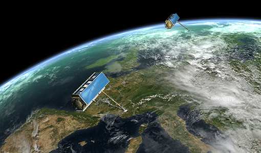
TerraSAR-X/TanDEM-X full archive and tasking
TerraSAR-X/TanDEM-X full archive and new tasking products can be acquired in six image modes with flexible resolutions (from 0.25 m to 40 m) and scene sizes and are provided in different packages: Staring SpotLight (basic, Interferometric pack, and Maritime pack) High Resolution SpotLight (basic, Interferometric pack, and Maritime pack) SpotLight (basic, Interferometric pack, and Maritime pack) StripMap (basic, Interferometric pack, and Maritime pack) ScanSAR (basic and Maritime pack) Wide ScanSAR (basic and Maritime pack) Product Overview Products SAR-ST SAR-HS SAR-SL SAR-SM SAR-SC SAR-WS Instrument mode Staring Spotlight High Resolution SpotLight SpotLight StripMap ScanSAR Wide ScanSAR Available resolutions (up to) 0.25 m 1 m 2 m 3 m 18 m 40 m Scene size 4x3.7 km2 10x5 km2 10x10 km2 30x50 km2 (up to 30x1650) 100x150 km2 (up to 100x1650) 270x200 km2 (up to 270x1500) Available processing levels SSC (Single Look Slant Range Complex): azimuth - slant range (time domain) MGD (Multi Look Ground Range Detected): azimuth - ground range (without terrain correction) GEC (Geocoded Ellipsoid Corrected): map geometry with ellipsoidal corrections only (no terrain correction performed) EEC (Enhanced Ellipsoid Corrected): map geometry with terrain correction, using a DEM Format SSC: DLR-defined COSAR binary MGD: GeoTiff GEC: GeoTiff EEC: GeoTiff Spatial coverage Worldwide Interferometry package InSAR-ST, InSAR-HS, InSAR-SL, InSAR-SM Only SSC At least five ordered scenes within six months from first order N/A N/A Maritime Monitoring package MmSAR-ST, MmSAR-HS, MmSAR-SL, MmSAR-SM, MmSAR-SC, MmSAR-WS Only SSC, MGD, GEC At least 75% of the scene area is water More than five ordered scenes in three months The following WorldDEM products can be requested: Products Description WorldDEMcore WorldDEMcore is output of interferometric processing of StripMap data pairs without any post-processing WorldDEMTM WorldDEMTM is produced based on WorldDEMcore, representing the surface of the Earth (including buildings, infrastructure and vegetation). Hydrological consistency is ensured WorldDEM DTM In additional editing steps, WorldDEMTMis transformed into a Digital Terrain Model (DTM) representing bare Earth elevation WorldDEM Bundle Includes WorldDEMTM, WorldDEM DTM, and Quality Layers The main specifications of the WorldDEM products are: Horizontal Coordinate Reference System: World Geodetic System 1984 (WGS84-G1150) Vertical Coordinate Reference System: Earth Gravitational Model 2008 (EGM2008) Absolute Horizontal Accuracy: <6 m Vertical Accuracy: 2 m Relative, 4 m Absolute Quality Layers (including water body mask) can be requested as an option with the WorldDEM and WorldDEM DTM Auxiliary Layers are delivered together with the WorldDEMcore product As per ESA policy, very high-resolution data over conflict areas cannot be provided.
Data - Fast Registration with approval (Restrained)
TerraSAR-X ESA archive
The TerraSAR-X ESA archive collection consists of TerraSAR-X and TanDEM-X products requested by ESA supported projects over their areas of interest around the world. The dataset regularly grows as ESA collects new products over the years. TerraSAR-X/TanDEM-X Image Products can be acquired in 6 image modes with flexible resolutions (from 0.25m to 40m) and scene sizes. Thanks to different polarimetric combinations and processing levels the delivered imagery can be tailored specifically to meet the requirements of the application. The following list delineates the characteristics of the SAR imaging modes that are disseminated under ESA Third Party Missions (TPM). StripMap (SM): Resolution 3 m, Scene size 30x50 km2 (up to 30x1650 km2) SpotLight (SL): Resolution 2 m, Scene size 10x10 km2 Staring SpotLight (ST): Resolution 0.25m, Scene size 4x3.7 km2 High Resolution SpotLight (HS): Resolution 1 m, Scene size 10x5 km2 ScanSAR (SC): Resolution 18 m, Scene size 100x150 km2 (up to 100x1650 km2) Wide ScanSAR (WS): Resolution 40 m, Scene size 270x200 km2 (up to 270x1500 km2) The following list briefly delineates the available processing levels for the TerraSAR-X dataset: SSC (Single Look Slant Range Complex) in DLR-defined COSAR binary format MGD (Multi Look Ground Range Detected) in GeoTiff format • GEC (Geocoded Ellipsoid Corrected) in GeoTiff format EEC (Enhanced Ellipsoid Corrected in GeoTiff format Spatial coverage: Check the spatial coverage of the collection on a map available on the Third Party Missions Dissemination Service. As per ESA policy, very high-resolution data over conflict areas cannot be provided.
Data - Fast Registration with approval (Restrained)

SPOT 6 and 7 ESA archive
The SPOT 6 and 7 ESA archive is a dataset of SPOT 6 and SPOT 7 products that ESA collected over the years. The dataset regularly grows as ESA collects new SPOT 6 and 7 products. SPOT 6 and 7 Primary and Ortho products can be available in the following modes: Panchromatic image at 1.5m resolution Pansharpened colour image at 1.5m resolution Multispectral image in 4 spectral bands at 6m resolution Bundle (1.5m panchromatic image + 6m multispectral image) Spatial coverage: Check the spatial coverage of the collection on a map available on the Third Party Missions Dissemination Service. As per ESA policy, very high-resolution imagery of conflict areas cannot be provided.
Data - Fast Registration with approval (Restrained)
SPOT 1-5 ESA archive
The ESA SPOT 1-5 collection is a dataset of SPOT 1 to 5 Panchromatic and Multispectral products that ESA collected over the years. The HRV(IR) sensor onboard SPOT 1-4 provides data at 10 m spatial resolution Panchromatic mode (-1 band) and 20 m (Multispectral mode -3 or 4 bands). The HRG sensor on board of SPOT-5 provides spatial resolution of the imagery to < 3 m in the panchromatic band and to 10 m in the multispectral mode (3 bands). The SWIR band imagery remains at 20 m. The dataset mainly focuses on European and African sites but some American, Asian and Greenland areas are also covered. Spatial coverage: Check the spatial coverage of the collection on a map available on the Third Party Missions Dissemination Service. The SPOT Collection
Data - Fast Registration with immediate access (Open)
Envisat RA-2 Sensor and Geophysical Data Record - SGDR [RA2_MWS__2P]
This is a RA-2 Sensor and Geophysical Data Record (SGDR) Full Mission Reprocessing (FMR) V3 product. This FMR follows the first Envisat Altimetry reprocessing Version (V2.1) completed in 2012. The GDR and S-GDR data products were reprocessed for all cycles from 6 to 113 (May 2002 to April 2012) into a homogeneous standard in NetCDF format (close to Sentinel-3). The Sensor Data Record (SGDR) Product from RA-2/MWR includes the data in the GDR product (RA-2 geophysical data, MWR data) and also RA-2 averaged waveforms (18Hz) and RA-2 individual waveforms (1800Hz). This product is a continuation of ERS RA data. This data product has a coverage of 1 pass and pole to pole, a spatial sampling of about 390 m along track and a size of 31 to 40 MB, depending on presence of individual waveforms. The radiometric accuracy is 0.2 dB and auxiliary data include: Orbit state vectors (DORIS, FOS), RA2 and MWR characterisation data, Platform attitude, Gain calibration, USO frequency, ECMWF data, time relation, leap second, Ionospheric corrections, geoid, mean sea surface, slope data, and tide model (ocean, earth, loading, pole). Please consult the Envisat RA-2/MWR Product Quality Readme file before using the data.
Data - Fast Registration with immediate access (Open)
Envisat RA-2 Geophysical Data Record - GDR [RA2_GDR__2P]
This is a RA-2 Geophysical Data Record (GDR) Full Mission Reprocessing (FMR) V3 product containing radar range and orbital altitude, wind speed, wave height, water vapour from the MWR and geophysical corrections. This FMR follows the first Envisat Altimetry reprocessing Version (V2.1) completed in 2012. The GDR and S-GDR data products were reprocessed for all cycles from 6 to 113 (May 2002 to April 2012) into a homogeneous standard in NetCDF format (close to Sentinel-3). For many aspects, the V3.0 reprocessed data are better than the previous dataset: In terms of available and valid data, the coverage is better, notably thanks to a better availability of MWR data at the beginning of the mission In terms of performance at cross-overs, the quality is improved: the annual signal and average of Mean SSH is decreased, as well as the standard deviation The new MWR characteristics were shown to improve largely the global quality of data. As well as the new tide model, the new MSS and the new orbit standard The Global and regional Mean Sea Level trend is very weakly impacted though the effort was put, this time, on the mesoscale restitution, rather than long term drift, as during V2.1 reprocessing. Please consult the Envisat RA-2/MWR Product Quality Readme file PDF before using the data.
Data - Project Proposal (Restrained)
Pléiades full archive and tasking
The Pléiades twins (1A and 1B) deliver very high-resolution optical data (up to 0.5 m resolution Panchromatic and Colour and 2 m Multispectral) and offer a daily revisit capability to any point on the globe. The swath width is approximately 20 km (with a nadir footprint). The ortho-products are automatically generated by the Pléiades ground segment, based on SRTM or Reference3D database. The projection available for Pléiades ortho-products is UTM, datum WGS84. Bands combinations:: Pansharpened: colour image at 0.5 m resolution Bundle: (0.5 m panchromatic image + 2 m multispectral image) Processing levels: Primary: The Primary product is the processing level closest to the natural image acquired by the sensor. This product restores perfect collection conditions: the sensor is placed in rectilinear geometry, and the image is clear of all radiometric distortion. Standard Ortho: The Ortho product is a georeferenced image in Earth geometry, corrected from acquisition and terrain off-nadir effects. Tailored Ortho: Aside from the Standard Ortho product, when different specifications are needed, a custom orthorectification, with a more precise 3D model provided by the client or acquired for the purpose, can be provided on demand. As per ESA policy, very high-resolution imagery of conflict areas cannot be provided.