- All Categories (33)
- Data (4)
- News (10)
- Missions (1)
- Events (12)
- Tools (1)
- Documents (5)
Tools - Visualisation
PROBA-V Mission Exploitation Platform (MEP)
The MEP PROBA-V addresses a broad vegetation user community with the final aim to ease and increase the use of PROBA-V data by any user.
News - General News
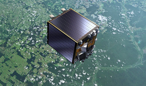
PROBA-V’s companion explores low-cost remote sensing
With the launch of PROBA-V’s Companion CubeSat (PV-CC), ESA supports a future where clusters of cheaper, small satellites could complement full-scale missions for Earth observation.
News - Spotlight on EO community
Meet one of ESA's first Africa Programme Research Fellows
Research Fellow, Dr Gladys Mosomtai, from the International Centre of Insect Physiology and Ecology (icipe), works on applying Earth observation data to better understand the spread of infectious disease in livestock, in Kenya.
News - Success Stories
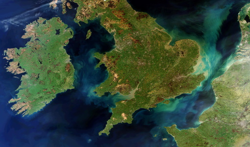
PROBA-V data improve surface albedo products in Africa
As ESA’s PROBA-V satellite marks its 10-year launch milestone, data tasked during the mission’s lifetime are still being used to assess changes in land cover.
Event - Meeting

PROBA-V QWG meeting 16
The Proba-V QWG meeting 16 – Hybrid Event: VITO (Mol) and Microsoft Teams held on 22-23 March 2023
News - Data Release news
PROBA-V ‘Collection 2’ - Reprocessed Dataset available
The improved PROBA-V data (Collection 2) has been released. Data is available via the PROBA-V MEP and Terrascope platforms so users can freely exploit the data using Virtual machines, Jupyter Notebooks, and the new viewing application.
News - Thematic area articles
Monitoring water on Earth's surface
ESA's Earth observation satellites are playing a leading role in furthering our understanding of how Earth's terrestrial hydrosphere is being influenced by humankind.
News - Thematic area articles
Global understanding of Earth's land surfaces greatly boosted by satellite data
ESA perform land surface monitoring with a range of instruments onboard satellites acquiring optical and radar data. Collections of data from these missions are freely available for research purposes.
Event - Meeting
PROBA-V QWG meeting 15
The Proba-V QWG meeting 15 - Hybrid Event: University of Valencia and Microsoft Teams held on 09-10 June 2022
News - Thematic area articles
Satellite data boost global understanding of land surface
Understanding our changing land surface is essential in the study of climate change. Satellites are used to monitor changes to the material that covers Earth’s surface, so-called land cover, such as vegetation and water.
Event - Meeting
PROBA-V QWG meeting 13
The status of the mission was recalled: Experimental Phase is running since July 2020 with the perspective to prepare the ground for the launch and exploitation of PV-CC mission. The latest delay in the schedule of the PV-CC launch (currently Q1/Q2 2022) changed the approach for exploitation, notably owing to the degrading Proba-V illumination conditions at the time of the launch. On the processing side, the main priority is to finalize the verification phase for the C2 and start the full mission reprocessing.
News - Success Stories
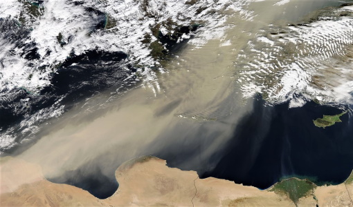
1 km resolution aerosol optical thickness retrieved from PROBA-V
The ESA SPAR@MEP project aims to deliver a long-term data record (LTDR) of aerosol optical properties and surface reflectance from SPOT-VGT and PROBA-V observations.
Event - Meeting
PROBA-V QWG meeting 12
The main discussion points for the QWG meeting #12 are recalled: 1. Mission Status: the operational phase was discontinued on 30 June 2020 to limit the impact of the orbital drift and the new experimental phase started on 1st July 2020 with focus on acquiring data over Africa and Europe together with ad-hoc acquisition campaigns. Flight and Ground Segment overall performances are excellent with no sign of degradation.
Data - Fast Registration with approval (Restrained)
RADARSAT-2 ESA archive
The RADARSAT-2 ESA archive collection consists of RADARSAT-2 products requested by ESA supported projects over their areas of interest around the world. The dataset regularly grows as ESA collects new products over the years. Following Beam modes are available: Standard, Wide Swath, Fine Resolution, Extended Low Incidence, Extended High Incidence, ScanSAR Narrow and ScanSAR Wide. Standard Beam Mode allows imaging over a wide range of incidence angles with a set of image quality characteristics which provides a balance between fine resolution and wide coverage, and between spatial and radiometric resolutions. Standard Beam Mode operates with any one of eight beams, referred to as S1 to S8, in single and dual polarisation . The nominal incidence angle range covered by the full set of beams is 20 degrees (at the inner edge of S1) to 52 degrees (at the outer edge of S8). Each individual beam covers a nominal ground swath of 100 km within the total standard beam accessibility swath of more than 500 km. Beam Mode Product Nominal Resolution (metres) Nominal Pixel Spacing Range x Azimuth (metres) Resolution Range x Azimuth (metres) Nominal Scene Size Range x Azimuth (kilometres) Range of Angle of Incidence (degrees) Number of Looks Range x Azimuth Polarisations Options Standard SLC 25 8.0 or 11.8 x 5.1 9.0 or 13.5 x 7.7 100 x 100 20 - 52 1 x 1 Single Pol HH or VV or HV or VH - or - Dual HH + HV or VV + VH SGX 8.0 x 8.0 26.8 - 17.3 x 24.7 1 x 4 SGF 12.5 x 12.5 SSG, SPG Wide Swath Beam Mode allows imaging of wider swaths than Standard Beam Mode, but at the expense of slightly coarser spatial resolution. The three Wide Swath beams, W1, W2 and W3, provide coverage of swaths of approximately 170 km, 150 km and 130 km in width respectively, and collectively span a total incidence angle range from 20 degrees to 45 degrees. Polarisation can be single and dual. Beam Mode Product Nominal Resolution (metres) Nominal Pixel Spacing Range x Azimuth (metres) Resolution Range x Azimuth (metres) Nominal Scene Size Range x Azimuth (kilometres) Range of Angle of Incidence (degrees) Number of Looks Range x Azimuth Polarisations Options Wide SLC 30 11.8 x 5.1 13.5 x 7.7 150 x 150 20 - 45 1 x 1 Single: Pol HH or VV or HV or VH - or - Dual: HH + HV or VV + VH SGX 10 x 10 40.0 - 19.2 x 24.7 1 x 4 SGF 12.5 x 12.5 SSG, SPG Fine Resolution Beam Mode is intended for applications which require finer spatial resolution. Products from this beam mode have a nominal ground swath of 50 km. Nine Fine Resolution physical beams, F23 to F21, and F1 to F6 are available to cover the incidence angle range from 30 to 50 degrees. For each of these beams, the swath can optionally be centred with respect to the physical beam or it can be shifted slightly to the near or far range side. Thanks to these additional swath positioning choices, overlaps of more than 50% are provided between adjacent swaths. RADARSAT-2 can operate in single and dual polarisation for this beam mode. Beam Mode Product Nominal resolution (metres) Nominal Pixel Spacing Range x Azimuth (metres) Resolution Range x Azimuth (metres) Nominal Scene Size Range x Azimuth (kilometres) Range of Angle of Incidence (degrees) Number of Looks Range x Azimuth Polarisations Options Fine SLC 8 4.7 x 5.1 5.2 x 7.7 50 x 50 30 - 50 1 x 1 Single: Pol HH or VV or HV or VH - or - Dual: HH + HV or VV + VH SGX 3.13 x 3.13 10.4 - 6.8 x 7.7 1 x 1 SGF 6.25 x 6.25 SSG, SPG In the Extended Low Incidence Beam Mode, a single Extended Low Incidence Beam, EL1, is provided for imaging in the incidence angle range from 10 to 23 degrees with a nominal ground swath coverage of 170 km. Some minor degradation of image quality can be expected due to operation of the antenna beyond its optimum scan angle range. Only single polarisation is available. Beam Mode Product Nominal resolution (metres) Nominal Pixel Spacing Range x Azimuth (metres) Resolution Range x Azimuth (metres) Nominal Scene Size Range x Azimuth (kilometres) Range of Angle of Incidence (degrees) Number of Looks Range x Azimuth Polarisations Options Extended Low SLC 25 8.0 x 5.1 9.0 x 7.7 170 x 170 10 - 23 1 x 1 Single: HH SGX 10.0 x 10.0 52.7 - 23.3 x 24.7 1 x 4 SGF 12.5 x 12.5 SSG, SPG In the Extended High Incidence Beam Mode, six Extended High Incidence Beams, EH1 to EH6, are available for imaging in the 49 to 60 degree incidence angle range. Since these beams operate outside the optimum scan angle range of the SAR antenna, some degradation of image quality, becoming progressively more severe with increasing incidence angle, can be expected when compared with the Standard Beams. Swath widths are restricted to a nominal 80 km for the inner three beams, and 70 km for the outer beams. Only single polarisation available. Beam Mode Product Nominal resolution (metres) Nominal Pixel Spacing Range x Azimuth (metres) Resolution Range x Azimuth (metres) Nominal Scene Size Range x Azimuth (kilometres) Range of Angle of Incidence (degrees) Number of Looks Range x Azimuth Polarisations Options Extended High SLC 25 11.8 x 5.1 13.5 x 7.7 75 x 75 49 - 60 1 x 1 Single Pol HH SGX 8.0 x 8.0 18.2 - 15.9 x 24.7 1 x 4 SGF 12.5 x 12.5 SSG, SPG ScanSAR Narrow Beam Mode provides coverage of a ground swath approximately double the width of the Wide Swath Beam Mode swaths. Two swath positions with different combinations of physical beams can be used: SCNA, which uses physical beams W1 and W2, and SCNB, which uses physical beams W2, S5, and S6. Both options provide coverage of swath widths of about 300 km. The SCNA combination provides coverage over the incidence angle range from 20 to 39 degrees. The SCNB combination provides coverage over the incidence angle range 31 to 47 degrees. RADARSAT-2 can operate in single and dual polarisation for this beam mode. Beam Mode Product Nominal resolution (metres) Nominal Pixel Spacing Range x Azimuth (metres) Resolution Range x Azimuth (metres) Nominal Scene Size Range x Azimuth (kilometres) Range of Angle of Incidence (degrees) Number of Looks Range x Azimuth Polarisations Options ScanSAR Narrow SCN, SCF, SCS 20 25 x 25 81 - 38 x 40 - 70 300 x 300 20 - 46 2 x 2 Single Co or Cross: HH or VV or HV or VH - or - Dual: HH + HV or VV + VH ScanSAR Wide Beam Mode provides coverage of a ground swath approximately triple the width of the Wide Swath Beam Mode swaths. Two swath positions with different combinations of physical beams can be used: SCWA, which uses physical beams W1, W2, W3, and S7, and SCWB, which uses physical beams W1, W2, S5 and S6. The SCWA combination allows imaging of a swath of more than 500 km covering an incidence angle range of 20 to 49 degrees. The SCWB combination allows imaging of a swath of more than 450 km covering the incidence angle. Polarisation can be single and dual. Beam Mode Product Nominal resolution (metres) Nominal Pixel Spacing Range x Azimuth (metres) Resolution Range x Azimuth (metres) Nominal Scene Size Range x Azimuth (kilometres) Range of Angle of Incidence (degrees) Number of Looks Range x Azimuth Polarisations Options ScanSAR Wide SCW, SCF, SCS 100 50 x 50 163 - 73 x 78 - 106 500 x 500 20 - 49 4 x 2 Single Co or Cross: HH or VV or HV or VH - or - Dual: HH + HV or VV + VH These are the different products : SLC (Single Look Complex): Amplitude and phase information is preserved. Data is in slant range. Georeferenced and aligned with the satellite track SGF (Path Image): Data is converted to ground range and may be multi-look processed. Scene is oriented in direction of orbit path. Georeferenced and aligned with the satellite track. SGX (Path Image Plus): Same as SGF except processed with refined pixel spacing as needed to fully encompass the image data bandwidths. Georeferenced and aligned with the satellite track SSG(Map Image): Image is geocorrected to a map projection. SPG (Precision Map Image): Image is geocorrected to a map projection. Ground control points (GCP) are used to improve positional accuracy. SCN(ScanSAR Narrow)/SCF(ScanSAR Wide) : ScanSAR Narrow/Wide beam mode product with original processing options and metadata fields (for backwards compatibility only). Georeferenced and aligned with the satellite track SCF (ScanSAR Fine): ScanSAR product equivalent to SGF with additional processing options and metadata fields. Georeferenced and aligned with the satellite track SCS(ScanSAR Sampled) : Same as SCF except with finer sampling. Georeferenced and aligned with the satellite track. Spatial coverage: Check the spatial coverage of the collection on a map available on the Third Party Missions Dissemination Service.
News - Operational News
New experimental phase for PROBA-V
PROBA-V has begun a new experimental phase that will continue through to October 2021.
Event - Meeting
PROBA-V QWG meeting 9
The 9th Proba-V QWG took place in Brussels on 17th - 18th Apr, 2019.
Event - Meeting
PROBA-V QWG meeting 10
The 10th PROBA-V Quality Working Group (QWG) meeting took place in Antwerp, Belgium on 23 and 24 October 2019.
News - Infographics
PROBA-V - ESA's vegetation monitoring mission
ESA's vegetation-monitoring mission - Proba-V - will end operations in June 2020 after seven years.
Data - External Data (Restrained)
PROBA-V 1 km, 333 m, and 100 m products
The PROBA-V VEGETATION Raw products and Synthesis products provided coverage of all significant landmasses worldwide with, in the case of a 10-day synthesis product, a minimum effect of cloud cover, resulting from selection of cloud-free acquisitions during the 10-day period. It provided a daily coverage between Latitudes 35°N and 75°N, and between 35°S and 56°S, and a full coverage every two days at the equator. The VEGETATION instrument was pre-programmed with an indefinite repeated sequence of acquisitions. This nominal acquisition scenario allowed a continuous series of identical products to be generated, with the goal to map land cover and vegetation growth across the entire planet every two days. Level Synthesis Resolution resolution (m) Reflectance Level-1C n/a TOA Level-2A n/a 100 m TOA 333 m TOA 1 km TOA Level-3 S1 100 m TOA TOC TOC NDVI 333 m TOA TOC 1 km TOA TOC S5 100 m TOA TOC TOC NDVI S10 333 m TOC TOC NDVI 1 km TOC TOC NDVI Raw Products Overview Product Description Level-1C Level-1C segments (P – product): Radiometrically corrected Level-1B data, in raw sensor geometry (unprojected) Contains: - Top Of Atmosphere reflectance in the four spectral bands - Longitude/latitude information for every pixel - Geometric viewing conditions - Information on the status map (indicating missing and interpolated measurements). Format: HDF5 & GeoTiFF Level-2A Level-2A segment: projected Level-1C (P–product) data, radiometrically and geometrically corrected. Contains: - TOA reflectance values in the four spectral bands without atmospheric correction being performed - Information on the status map (containing identification of radiometric quality, snow, ice, shadow, clouds, land/sea for every pixel) - Geometric viewing conditions Plate carrée projection (EPSG:4326) with spatial resolution of 100 m, 333 m and 1 km Format: HDF5 & GeoTiFF Synthesis Products Overview Level-3 S1 = daily, S5 = 5 days, S10 = decade Different spatial resolution: 100 m, 333 m and 1 km Divided into so called granules, each measuring 10 degrees x 10 degrees, each granule being delivered as a single file Plate carrée projection (EPSG:4326) Format: HDF5 & GeoTiFF Products Content TOA - Top Of Atmosphere reflectance in the four spectral bands (no atmospheric correction applied) - Normalized Difference Vegetation Index (NDVI) -Information on the composite status map (containing identification of snow, ice, shadow, clouds, land/sea for every pixel) - Geometric viewing conditions & date and time of selected measurement TOC Level-2A segment: projected Level-1C (P–product) data, radiometrically and geometrically corrected. Contains: - Top Of Canopy (ground surface) reflectance in the four spectral bands, the atmospheric correction being performed using the SMAC (Simplified Method for Atmospheric Corrections) algorithm - Normalized Difference Vegetation Index (NDVI) - Information on the composite status map (containing identification of snow, ice, shadow, clouds, land/sea for every pixel) Normalized Difference Vegetation Index (NDVI) from Top Of Canopy product (SMAC algorithm for atmospheric corrections applied) - Geometric viewing conditions & date and time of selected measurement TOC NDVI Normalized Difference Vegetation Index (NDVI) from Top Of Canopy product (SMAC algorithm for atmospheric corrections applied)