- All Categories (122)
- Data (18)
- News (23)
- Missions (6)
- Events (15)
- Tools (1)
- Activities (1)
- Campaigns (5)
- Documents (53)
DATA
Discover and download the Earth observation data you need from the broad catalogue of missions the European Space Agency operate and support.
Data - EO Sign In Authentication (Open)

EarthCARE JAXA L2 Products
This EarthCARE collection contains the following data products: Level 2a: Single-Instrument Geophysical Products These products are derived from individual instrument data onboard EarthCARE. They provide detailed geophysical parameters and properties specific to each instrument's capabilities for example cloud and aerosol properties derived solely from radar or lidar measurements, offering high-resolution insights into atmospheric phenomena. Level 2b: Synergistic Geophysical Products Level 2b products leverage data from multiple EarthCARE instruments to generate comprehensive, synergistic geophysical datasets. By combining measurements from instruments like radar, lidar, and radiometers, these products offer a more integrated view of cloud-aerosol interactions and atmospheric dynamics. Synergistic products provide enhanced accuracy and depth compared to single-instrument outputs, enabling detailed studies of complex atmospheric processes.
Data - EO Sign In Authentication (Open)
EarthCARE ESA L2 Products
This EarthCARE collection contains the following data products: Level 2a: Single-Instrument Geophysical Products These products are derived from individual instrument data onboard EarthCARE. They provide detailed geophysical parameters and properties specific to each instrument's capabilities for example cloud and aerosol properties derived solely from radar or lidar measurements, offering high-resolution insights into atmospheric phenomena. Level 2b: Synergistic Geophysical Products Level 2b products leverage data from multiple EarthCARE instruments to generate comprehensive, synergistic geophysical datasets. By combining measurements from instruments like radar, lidar, and radiometers, these products offer a more integrated view of cloud-aerosol interactions and atmospheric dynamics. Synergistic products provide enhanced accuracy and depth compared to single-instrument outputs, enabling detailed studies of complex atmospheric processes.
Data - EO Sign In Authentication (Open)
EarthCARE L1 Products
This EarthCARE collection contains the following data products: Level 1b: Fully Calibrated and Geolocated Instrument Science Measurements Level 1b data represents the fully processed, calibrated, and geolocated measurements from EarthCARE's instruments. Each measurement is aligned with the native instrument grid. For the Broadband Radiometer (BBR), measurements are also spatially integrated to various ground pixel sizes. Level 1c (MSI only): MSI Level 1b Data Interpolated to a Common Spatial Grid Specifically for the Multi-Spectral Imager (MSI), Level 1c data involves interpolating Level 1b measurements onto a standardised spatial grid that is consistent across all MSI bands. This grid closely matches the spacing used in MSI Level 1b data. Level 1d: Joint Standard Grid (JSG) for all instruments with ECMWF Meteorological Fields. Level 1d data provides a spatial grid to enable easy collocation and synergistic use of the data from all EarthCARE instruments, named the "joint standard grid." Additionally, this level incorporates ECMWF (European Centre for Medium-Range Weather Forecasts) meteorological fields limited to the EarthCARE swath, enabling comprehensive analysis and modelling of atmospheric conditions within the satellite's coverage area. CPR level 1b: C-NOM products is generated and provided by JAXA. This product is used as input, in combination with the X-MET aux file, for different processors in the EarthCARE production chain. AUX_MET_1D: meteorological analysis and forecast fields X-MET provided by ECMWF. This product is used as input, in combination with the C-NOM product, for different processors in the EarthCARE production chain.
Data - EO Sign In Authentication (Open)
EarthCARE Orbit Data
EarthCARE data products encompass essential supporting auxiliary (AUX) and orbit data critical for accurate sensor data processing and analysis. Orbit data consists of on-board satellite data and orbital information predicted or determined by the Flight Operations Segment (FOS). For EarthCARE, this includes Reconstructed Orbit and Attitude Files, which provide detailed satellite positioning and orientation information. The integration of AUX and orbit data into EarthCARE's data processing workflow ensures the production of high-quality, scientifically valuable datasets for atmospheric research, climate modelling, and environmental monitoring.
Data - Restrained Access (Restrained)
EarthCARE ESA L2 Products for the Commissioning Team
This EarthCARE collection contains the following data products: Level 2a: Single-Instrument Geophysical Products These products are derived from individual instrument data onboard EarthCARE. They provide detailed geophysical parameters and properties specific to each instrument's capabilities for example cloud and aerosol properties derived solely from radar or lidar measurements, offering high-resolution insights into atmospheric phenomena. Level 2b: Synergistic Geophysical Products Level 2b products leverage data from multiple EarthCARE instruments to generate comprehensive, synergistic geophysical datasets. By combining measurements from instruments like radar, lidar, and radiometers, these products offer a more integrated view of cloud-aerosol interactions and atmospheric dynamics. Synergistic products provide enhanced accuracy and depth compared to single-instrument outputs, enabling detailed studies of complex atmospheric processes.
Data - Restrained Access (Restrained)
EarthCARE Auxiliary Data for Cal/Val Users
EarthCARE data products encompass essential supporting auxiliary (AUX) and orbit data critical for accurate sensor data processing and analysis. AUX data includes datasets used outside the primary Space Segment stream to apply corrections to sensor data. This comprises previously derived calibration parameters, ground control data, and digital elevation data. Calibration parameters ensure measurement accuracy, while ground control data aids in data validation, and digital elevation data enables precise geolocation. Orbit data consists of on-board satellite data and orbital information. For EarthCARE, this includes Reconstructed Orbit and Attitude Files, which provide detailed satellite positioning and orientation information. The integration of AUX and orbit data into EarthCARE's data processing workflow ensures the production of high-quality, scientifically valuable datasets for atmospheric research, climate modelling, and environmental monitoring.
Data - Restrained Access (Restrained)
EarthCARE L0 and L1 Products for the Commissioning Team
This EarthCARE collection for the Commissioning Team contains the following data products: Level 0: Annotated Raw Instrument Source Packets These packets contain unprocessed data as generated by EarthCARE's instruments, annotated with basic metadata in front of each packet Level 1b: Fully Calibrated and Geolocated Instrument Measurements Level 1b products are fully processed, calibrated, and geolocated measurements from EarthCARE's instruments. Each measurement is aligned with the native instrument grid. For the Broadband Radiometer (BBR), measurements are also spatially integrated to various ground pixel sizes. Level 1C (MSI only): MSI Level 1b Data Interpolated to a Common Spatial Grid Specifically for the Multi-Spectral Imager (MSI), Level 1c data involves interpolating Level 1b measurements onto a standardised spatial grid that is consistent across all MSI bands. This grid closely matches the spacing used in MSI Level 1b data. Level 1D: Joint Standard Grid (JSG) for all Instruments and ECMWF Meteorological Fields Level 1d data provide a spatial grid to enable easy collocation and synergistic use of the data from all EarthCARE instruments, named the "joint standard grid." Additionally, this level incorporates ECMWF (European Centre for Medium-Range Weather Forecasts) meteorological fields limited to the EarthCARE swath, enabling comprehensive analysis and modelling of atmospheric conditions within the satellite's coverage area.
Data - Restrained Access (Restrained)
EarthCARE L1 Products for Cal/Val Users
This EarthCARE collection is restrained, and contains the following data products: Level 1B: Fully Calibrated and Geolocated Instrument Science Measurements Level 1b data represents the fully processed, calibrated, and geolocated measurements from EarthCARE's instruments. Each measurement is aligned with the native instrument grid. For the Broadband Radiometer (BBR), measurements are also spatially integrated to various ground pixel sizes. Level 1C (MSI only): MSI Level 1b Data Interpolated to a Common Spatial Grid Specifically for the Multi-Spectral Imager (MSI), Level 1c data involves interpolating Level 1b measurements onto a standardised spatial grid that is consistent across all MSI bands. This grid closely matches the spacing used in MSI Level 1b data. Level 1D: Joint Standard Grid (JSG) for all instruments with ECMWF Meteorological Fields. Level 1d data provides a spatial grid to enable easy collocation and synergistic use of the data from all EarthCARE instruments, named the "joint standard grid." Additionally, this level incorporates ECMWF (European Centre for Medium-Range Weather Forecasts) meteorological fields limited to the EarthCARE swath, enabling comprehensive analysis and modelling of atmospheric conditions within the satellite's coverage area.
Data - Restrained Access (Restrained)
EarthCARE ESA L2 Products for Cal/Val Users
This EarthCARE collection is restrained, and contains the following data products: Level 2a: Single-Instrument Geophysical Products These products are derived from individual instrument data onboard EarthCARE. They provide detailed geophysical parameters and properties specific to each instrument's capabilities for example cloud and aerosol properties derived solely from radar or lidar measurements, offering high-resolution insights into atmospheric phenomena. Level 2b: Synergistic Geophysical Products Synergistic Geophysical Products Level 2b products leverage data from multiple EarthCARE instruments to generate comprehensive, synergistic geophysical datasets. By combining measurements from instruments like radar, lidar, and radiometers, these products offer a more integrated view of cloud-aerosol interactions and atmospheric dynamics. Synergistic products provide enhanced accuracy and depth compared to single-instrument outputs, enabling detailed studies of complex atmospheric processes.
Data - Restrained Access (Restrained)
EarthCARE JAXA L2 Products for Cal/Val Users
This EarthCARE collection is restrained, and contains the following data products: Level 2a: Single-Instrument Geophysical Products These products are derived from individual instrument data onboard EarthCARE. They provide detailed geophysical parameters and properties specific to each instrument's capabilities for example cloud and aerosol properties derived solely from radar or lidar measurements, offering high-resolution insights into atmospheric phenomena. Level 2b: Synergistic Geophysical Products Level 2b products leverage data from multiple EarthCARE instruments to generate comprehensive, synergistic geophysical datasets. By combining measurements from instruments like radar, lidar, and radiometers, these products offer a more integrated view of cloud-aerosol interactions and atmospheric dynamics. Synergistic products provide enhanced accuracy and depth compared to single-instrument outputs, enabling detailed studies of complex atmospheric processes.
Data - Restrained Access (Restrained)
EarthCARE JAXA L2 Products for the Commissioning Team
This EarthCARE collection contains the following data products: Level 2a: Single-Instrument Geophysical Products These products are derived from individual instrument data onboard EarthCARE. They provide detailed geophysical parameters and properties specific to each instrument's capabilities for example cloud and aerosol properties derived solely from radar or lidar measurements, offering high-resolution insights into atmospheric phenomena. Level 2b: Synergistic Geophysical Products Level 2b products leverage data from multiple EarthCARE instruments to generate comprehensive, synergistic geophysical datasets. By combining measurements from instruments like radar, lidar, and radiometers, these products offer a more integrated view of cloud-aerosol interactions and atmospheric dynamics. Synergistic products provide enhanced accuracy and depth compared to single-instrument outputs, enabling detailed studies of complex atmospheric processes.
Data - Project Proposal (Restrained)
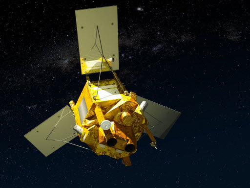
SPOT-6 to 7 full archive and tasking
The SPOT 6 and 7 satellites ensure data continuity with the no longer operational SPOT 5 satellite and provide an archive of very high resolution optical acquisition as well as the possibility to task the satellites for new acquisitions. Following the completion of the SPOT 7 mission in March 2023, new acquisition tasking is only available for the SPOT 6 satellite. The ortho-products are automatically generated by the SPOT 6 and 7 ground segment, based on SRTM database or Reference3D when available. The projection available for SPOT 6 and 7 ortho-products is UTM, datum WGS84. Bands combinations: Pansharpened: colour image at 1.5 m resolution Bundle: 1.5 m panchromatic image and 6 m multispectral image. Geometric processing levels: Primary: The Primary product is the processing level closest to the natural image acquired by the sensor. This product restores perfect collection conditions: the sensor is placed in rectilinear geometry, and the image is clear of all radiometric distortion. Standard Ortho: The Ortho product is a georeferenced image in Earth geometry, corrected from acquisition and terrain off-nadir effects. Tailored ortho: Aside from the Standard Ortho product, when different specifications are needed, a custom orthorectification, with a more precise 3D model provided by the client or acquired for the purpose, can be provided on demand. As per ESA policy, very high-resolution imagery of conflict areas cannot be provided.
Data - EO Sign In Authentication (Open)
AVHRR Level-1B Local Area Coverage Imagery
This collection is composed of AVHRR L1B products (1.1 km) reprocessed from the NOAA POES and Metop AVHRR sensors data acquired at the University of Dundee and University of Bern ground stations and from the ESA and University of Bern data historical archive. The product format is the NOAA AVHRR Level 1B that combines the AVHRR data from the HRPT stream with ancillary information like Earth location and calibration data which can be applied by the user. Other appended parameters are time codes, quality indicators, solar and satellite angles and telemetry. Two data collections cover Europe and the neighbouring regions in the period of 1 January 1981 to 31 December 2020 and the acquired data in the context of the 1-KM project in the ‘90s. During the early 1990’s various groups, including the International Geosphere-Biosphere Programme (IGBP), the Commission of the European Communities (CEC), the Moderate Resolution Imaging Spectrometer (MODIS) Science Team and ESA concluded that a global land 1 KM AVHRR data set would have been crucial to study and develop algorithms for several land products for the Earth Observing System. USGS, NOAA, ESA and other non-U.S. AVHRR receiving stations endorsed the initiative to collect a global land 1-km multi-temporal AVHRR data set over all land surfaces using NOAA's TIROS "afternoon" polar-orbiting satellite. On 1 April 1992, the project officially began up to the end of 1999 with the utilisation of 23 stations worldwide plus the NOAA local area coverage (LAC) on-board recorders. The global land 1-km AVHRR dataset is composed of 5 channels, raw AVHRR dataset at 1.1 km resolution from the NOAA-11 and NOAA-14 satellites covering land surfaces, inland water and coastal areas. Global Land 1 km AVHRR Data Set Project HRPT Ground Station Network (as of 1 April 1992) and Acquisition Areas for LAC Recorded Data Spatial coverage: Check the spatial coverage of the collection on a map available on the Third Party Missions Dissemination Service: AVHRR L1B 1.1 KM AVHRR L1B LAC Out-of-Europe.
Data - Campaigns (Open)

EPATAN 2016
The main scientific objectives of EPATAN 2016 (Earthcare PrepAraTion cAmpaigN) were derived from the scientific objectives of EarthCARE.
Data - Fast Registration with approval (Restrained)

SPOT 6 and 7 ESA archive
The SPOT 6 and 7 ESA archive is a dataset of SPOT 6 and SPOT 7 products that ESA collected over the years. The dataset regularly grows as ESA collects new SPOT 6 and 7 products. SPOT 6 and 7 Primary and Ortho products can be available in the following modes: Panchromatic image at 1.5m resolution Pansharpened colour image at 1.5m resolution Multispectral image in 4 spectral bands at 6m resolution Bundle (1.5m panchromatic image + 6m multispectral image) Spatial coverage: Check the spatial coverage of the collection on a map available on the Third Party Missions Dissemination Service. As per ESA policy, very high-resolution imagery of conflict areas cannot be provided.
Data - Project Proposal (Restrained)
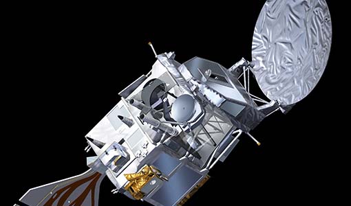
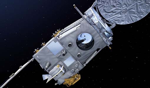
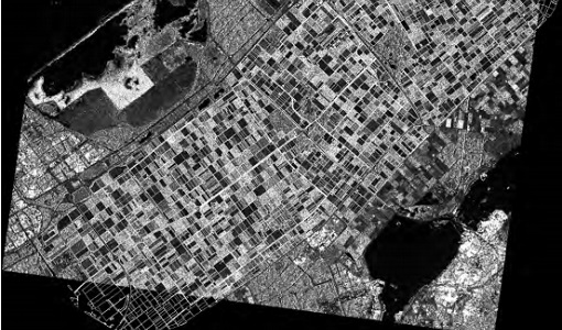
RADARSAT-1 & 2 full archive and tasking
RADARSAT-1 products The Standard beam mode operates with any one of seven beam positions, referred to as S1 to S7. The nominal incidence angle range covered by the full set of Standard beams is from 20 degrees (at the inner edge of S1) to 49 degrees (at the outer edge of S7). Each individual beam covers a minimum ground swath of 100 km within the total 500 km accessibility swath of the full set of Standard beams. The nominal spatial resolution in the range direction is 26 m for S1 at near range to 20 m for S7 at far range. The nominal azimuth resolution is the same, 27 m, for all beam positions. The Wide beam modes are similar to the Standard beams except that the swath width achieved by this beam is 150 km rather than 100 km. As a result, only three Wide beams, W1, W2 and W3 are necessary to provide coverage of almost all of the 500 km swath range. They provide comparable resolution to the standard beam mode, though the increased ground swath coverage is obtained at the expense of a slight reduction in overall image quality. In the Fine beam mode the nominal azimuth resolution is 8.4 m, with range resolution 9.1 m to 7.8 m from F1 to F5. Since the radar operates with a higher sampling rate in this mode than in any of the other beam mode, the ground swath coverage has to be reduced to approximately 50 km in order to keep the downlink signal within its allocated bandwidth. Originally, five Fine beam positions, F1 to F5, were available to cover the far range of the swath with an incidence angle range from 37 to 47 degrees. By modifying timing parameters, 10 new positions have been added with offset ground coverage. Each original Fine beam position can either be shifted closer to or further away from Nadir. In Extended High beam mode six positions, EH1 to EH6, are available for collection of data in the 49 to 60 degree incidence angle range. Since this beam mode operates outside the optimum scan angle range of the SAR antenna, some minor degradation of image quality can be expected when compared with the Standard beam mode. Swath widths are restricted to a nominal 80 km for the inner three positions, and 70 km for the outer three positions. In Extended Low beam mode one position, EL1, is provided for imaging in the incidence angle range 10 to 23 degrees with nominal ground swath coverage of 170 km. As with the Extended High beam mode, some minor degradation of image quality can be expected due to operation of the antenna beyond its optimum elevation angle range. In ScanSAR mode, combinations of two, three or four single beams are used during data collection. Each beam is selected sequentially so that data is collected from a wider swath than possible with a single beam. The beam switching rates are chosen to ensure at least one "look" at the Earth's surface for each beam within the along track illumination time or dwell time of the antenna beam. In practice, the radar beam switching is adjusted to provide two looks per beam. The beam multiplexing inherent in ScanSAR operation reduces the effective sampling rate within each of the component beams; hence the increased swath coverage is obtained at the expense of spatial resolution. The ScanSAR Narrow mode combines two beams (incidence angle range of 20 to 39 degrees) or three beams (incidence angle from 31 to 46 degrees) and provides coverage of a nominal 300 km ground swath, with spatial resolution of 50 m. The ScanSAR Wide mode combines four beams, provides coverage of either 500 km (with incidence angle range of 20 to 49 degrees) or 450 km (incidence angle range from 20 to 46 degrees) nominal ground swaths depending on the beam combination. Beam Mode Product Ground coverage (km2) Nominal resolution (m) Polarisation ScanSAR wide SCW, SCF, SCS 500 x 500 100 Single and dual ScanSAR narrow SCN, SCF, SCS 300 x 300 60 Single and dual Wide SGF, SGX, SLC, SSG, SPG 150 x 150 24 Single and dual Standard SGF, SGX, SLC, SSG, SPG 100 x 100 24 Single Extended low SGF, SGX, SLC, SSG, SPG 170 x 170 24 Single Extended high SGF, SGX, SLC, SSG, SPG 75 x 75 24 Single Fine SGF, SGX, SLC, SSG, SPG 50 x 50 8 Single RADARSAT-2 products The Standard Beam Mode allows imaging over a wide range of incidence angles with a set of image quality characteristics which provides a balance between fine resolution and wide coverage, and between spatial and radiometric resolutions. Standard Beam Mode operates with any one of eight beams, referred to as S1 to S8. The nominal incidence angle range covered by the full set of beams is 20 degrees (at the inner edge of S1) to 52 degrees (at the outer edge of S8). Each individual beam covers a nominal ground swath of 100 km within the total standard beam accessibility swath of more than 500 km. The Wide Swath Beam Mode allows imaging of wider swaths than Standard Beam Mode, but at the expense of slightly coarser spatial resolution. The three Wide Swath beams, W1, W2 and W3, provide coverage of swaths of approximately 170 km, 150 km and 130 km in width respectively, and collectively span a total incidence angle range from 20 degrees to 45 degrees. The Fine Resolution Beam Mode is intended for applications which require finer spatial resolution. Products from this beam mode have a nominal ground swath of 50 km. Nine Fine Resolution physical beams, F23 to F21, and F1 to F6 are available to cover the incidence angle range from 30 to 50 degrees. For each of these beams, the swath can optionally be centred with respect to the physical beam or it can be shifted slightly to the near or far range side. Thanks to these additional swath positioning choices, overlaps of more than 50% are provided between adjacent swaths. In the Extended Low Incidence Beam Mode, a single Extended Low Incidence Beam, EL1, is provided for imaging in the incidence angle range from 10 to 23 degrees with a nominal ground swath coverage of 170 km. Some minor degradation of image quality can be expected due to operation of the antenna beyond its optimum scan angle range. In the Extended High Incidence Beam Mode, six Extended High Incidence Beams, EH1 to EH6, are available for imaging in the 49 to 60 degree incidence angle range. Since these beams operate outside the optimum scan angle range of the SAR antenna, some degradation of image quality, becoming progressively more severe with increasing incidence angle, can be expected when compared with the Standard Beams. Swath widths are restricted to a nominal 80 km for the inner three beams, and 70 km for the outer beams. ScanSAR Narrow Beam Mode provides coverage of a ground swath approximately double the width of the Wide Swath Beam Mode swaths. Two swath positions with different combinations of physical beams can be used: SCNA, which uses physical beams W1 and W2, and SCNB, which uses physical beams W2, S5, and S6. Both options provide coverage of swath widths of about 300 km. The SCNA combination provides coverage over the incidence angle range from 20 to 39 degrees. The SCNB combination provides coverage over the incidence angle range 31 to 47 degrees. ScanSAR Wide Beam Mode provides coverage of a ground swath approximately triple the width of the Wide Swath Beam Mode swaths. Two swath positions with different combinations of physical beams can be used: SCWA, which uses physical beams W1, W2, W3, and S7, and SCWB, which uses physical beams W1, W2, S5 and S6. The SCWA combination allows imaging of a swath of more than 500 km covering an incidence angle range of 20 to 49 degrees. The SCWB combination allows imaging of a swath of more than 450 km covering the incidence angle. In the Standard Quad Polarization Beam Mode, the radar transmits pulses alternately in horizontal (H) and vertical (V) polarisations, and receives the return signals from each pulse in both H and V polarisations separately but simultaneously. This beam mode therefore enables full polarimetric (HH+VV+HV+VH) image products to be generated. The Standard Quad Polarization Beam Mode operates with the same pulse bandwidths as the Standard Beam Mode. Products with swath widths of approximately 25 km can be obtained covering any area within the region from an incidence angle of 18 degrees to at least 49 degrees. The Wide Standard Quad Polarization Beam Mode operates the same way as the Standard Quad Polarization Beam Mode but with higher data acquisition rates, and offers wider swaths of approximately 50 km at equivalent spatial resolution. 21 beams are available covering any area from 18 degrees to 42 degrees, ensuring overlaps of about 50% between adjacent swaths. The Fine Quad Polarization Beam Mode provides full polarimetric imaging with the same spatial resolution as the Fine Resolution Beam Mode. Fine Quad Polarization Beam Mode products with swath widths of approximately 25 km can be obtained covering any area within the region from an incidence angle of 18 degrees to at least 49 degrees. The Wide Fine Quad Polarization Beam Mode operates the same way as the Fine Quad Polarization Beam Mode but with higher data acquisition rates, and offers a wider swath of approximately 50 km at equivalent spatial resolution. 21 beams are available covering any area from 18 degrees to 42 degrees, ensuring overlaps of about 50% between adjacent swaths. The Multi-Look Fine Resolution Beam Mode covers the same swaths as the Fine Resolution Beam Mode. Products with multiple looks in range and azimuth are generated at approximately the same spatial resolution as Fine Resolution Beam mode products, but with multiple looks and therefore improved radiometric resolution. Single look products are generated at finer spatial resolutions than Fine Resolution Beam Mode products. In order to obtain the multiple looks without a reduction in swath width, this beam mode operates with higher data acquisition rates and noise levels than Fine Resolution Beam Mode. As with the Fine Resolution Beam Mode, nine physical beams are available to cover the incidence angle range from 30 to 50 degrees, and additional near and/or far range swath positioning choices are available to provide additional overlap. The Wide Multi-Look Fine Resolution Beam Mode offers a wider coverage alternative to the regular Multi-Look Fine Beam Mode, while preserving the same spatial and radiometric resolution, but at the expense of higher data compression ratios (which leads to higher signal-dependent noise levels). The nominal swath width is 90 km compared to 50 km for the Multi-Look Fine Beam Mode. The nine physical beams are the same as in the Multi-Look Fine Beam Mode, covering incidence angles from approximately 30 to 50 degrees, but the additional near and far range swath positioning choices available in the Multi-Look Fine Beam Mode are not needed because the beam centered swaths are wide enough to overlap by more than 50%. The Ultra-Fine Resolution Beam Mode is intended for applications which require very high spatial resolution. The set of Ultra-Fine Resolution Beams cover any area within the incidence angle range from 20 to 50 degrees (soon to be extended to 54 degrees). Each beam within the set images a swath width of at least 20 km. The Wide Ultra-Fine Resolution Beam Mode provides the same spatial resolution as the Ultra-Fine mode as well as wider coverage, but at the expense of higher data compression ratios (which leads to higher signal-dependent noise levels). The set of Wide Ultra-Fine Resolution Beams cover any area within the incidence angle range from 30 to 50 degrees. Each beam within the set images a swath width of approximately 50 km. The Wide Fine Resolution Beam Mode is intended for applications which require both a finer spatial resolution and a wide swath. Products from this beam mode have a nominal ground swath equivalent to the ones offered by the Wide Swath Beam Mode (170 km, 150 km and 120 km) and a spatial resolution equivalent to the ones offered by the Fine Resolution Beam Mode, at the expense of somewhat higher noise levels. Three Wide Fine Resolution beam positions, F0W1 to F0W3 are available to cover the incidence angle range from 20 to 45 degrees. The Extra-Fine Resolution Beam Mode nominally provides similar swath width and incidence angle coverage as the Wide Fine Beam Mode, at even finer resolutions, but with higher data compression ratios and noise levels. The four Extra-Fine beams provide coverage of swaths of approximately 160 km, 124 km, 120 km and 108 km in width respectively, and collectively span a total incidence angle range from 22 to 49 degrees. This beam mode also offers additional optional processing parameter selections that allow for reduced-bandwidth single-look products, 4-look, and 28-look products. In Spotlight Beam Mode, the beam is steered electronically in order to dwell on the area of interest over longer aperture times, which allows products to be processed to finer azimuth resolution than in other modes. Unlike in other modes, Spotlight images are of fixed size in the along track direction. The set of Spotlight beams cover any area within the incidence angle range from 20 to 50 degrees (soon to be extended to 54 degrees). Each beam within the set images a swath width of at least 18 km. Beam Mode Product Nominal Pixel Spacing [Range x Azimuth] (metres) Nominal Resolution (metres) Resolution [Range x Azimuth] (metres) Nominal Scene Size [Range x Azimuth] (kilometres) Range of Angle of Incidence [Range] (degrees) Number of Looks [Range x Azimuth] Polarisations Options Spotlight SLC 1.3 x 0.4 <1 1.6 x 0.8 18 x 8 20 to 54 1 x 1 Single Co or Cross (HH or VV or HV or VH) SGX 1 or 0.8 x 1/3 4.6 - 2.0 x 0.8 SGF 0.5 x 0.5 SSG, SPG Ultra-fine SLC 1.3 x 2.1 3 1.6 x 2.8 20 x 20 20 to 54 1 x 1 Single Co or Cross (HH or VV or HV or VH) SGX 1 x 1 or 0.8 x 0.8 3.3 – 2.1 x 2.8 SGF 1.56 x 1.56 SSG, SPG Wide Ultra-fine SLC 1.3 x 2.1 3 3.1 x 4.6 50 x 50 29 to 50 1 x 1 Single Co or Cross (HH or VV or HV or VH) SGX 1 x 1 3.3 - 2.1 x 2.8 SGF 1.56 x 1.56 SSG, SPG Multi-look fine SLC 2.7 x 2.9 8 3.1 x 4.6 50 x 50 30 to 50 1 x 1 Single Co or Cross (HH or VV or HV or VH) SGX 3.13 x 3.13 10.4 - 6.8 x 7.6 2 x 2 SGF 6.25 x 6.25 SSG, SPG Wide Multi-look fine SLC 2.7 x 2.9 8 3.1 x 4.6 90 x 50 29 to 50 1 x 1 Single Co or Cross (HH or VV or HV or VH) SGX 3.13 x 3.13 10.8 - 6.8 x 7.6 2 x 2 SGF 6.25 x 6.25 SSG, SPG Extra-fine SLC (Full resolution) 2.7 x 2.9 5 3.1 x 4.6 125 x 125 22 to 49 1 x 1 Single Co or Cross (HH or VV or HV or VH) SLC (fine resolution) 4.3 x 5.8 5.2 x 7.6 SLC (standard resolution) 7.1 x 5.8 8.9 x 7.6 SLC (wide resolution) 10.6 x 5.8 13.3 x 7.6 SGX (1 look) 2.0 x 2.0 8.4 – 4.1 x 4.6 SGX (4 looks) 3.13 x 3.13 14 – 6.9 x 7.6 2 x 2 SGX (28 looks) 5.0 x 5.0 24 - 12 x 23.5 4 x 7 SGF (1 look) 3.13 x 3.13 8.4 - 4.1 x 4.6 1 x 1 SGF (4 looks) 6.25 x 6.25 14 - 6.9 x 7.6 2 x 2 SGF (28 looks) 8.0 x 8.0 24 - 12 x 23.5 4 x 7 SSG, SPG 3.13 x 3.13 8.4 - 4.1 x 4.6 1 x 1 Fine SLC 4.7 x 5.1 8 5.2 x 7.7 50 x 50 30 to 50 1 x 1 Single Co or Cross (HH or VV or HV or VH) or Dual (HH+HV or VV+VH) SGX 3.13 x 3.13 10.4 – 6.8 x 7.7 SGF 6.25 x 6.25 SSG, SPG Wide Fine SLC 4.7 x 5.1 8 5.2 x 7.7 150 x 150 20 to 45 1 x 1 Single Co or Cross (HH or VV or HV or VH) or Dual (HH+HV or VV+VH) SGX 3.13 x 3.13 14.9 - 7.3 x 7.7 SGF 6.25 x 6.25 SSG, SPG Standard SLC 8.0 or 11.8 x 5.1 25 9.0 or 13.5 x 7.7 100 x 100 20 - 52 1 x 1 Single Co or Cross (HH or VV or HV or VH) or Dual (HH+HV or VV+VH) SGX 8 x 8 26.8 - 17.3 x 24.7 1 x 4 SGF 12.5 x 12.5 SSG, SPG Wide SLC 11.8 x 5.1 30 13.5 x 7.7 150 x 150 20 - 45 1 x 1 Single Co or Cross (HH or VV or HV or VH) or Dual (HH+HV or VV+VH) SGX 10 x 10 40.0 - 19.2 x 24.7 1 x 4 SGF 12.5 x 12.5 SSG, SPG Extended High SLC 11.8 x 5.1 25 13.5 x 7.7 75 x 75 49 - 60 1 x 1 Single (HH only) SGX 8 x 8 18.2 - 15.9 x 24.7 1 x 4 SGF 12.5 x 12.5 SSG, SPG Extended Low SLC 8.0 x 5.1 25 9.0 x 7.7 170 x 170 10 - 23 1 x 1 Single (HH only) SGX 10 x 10 52.7 – 23.3 x 24.7 1 x 4 SGF 12.5 x 12.5 SSG, SPG Fine Quad-Pol SLC 4.7 x 5.1 8 5.2 x 7.6 25 x 25 18 - 49 1 x 1 Quad (HH+VV+HV+VH) SGX 3.13 x 3.13 16.5 – 6.8 x 7.6 1 x 1 SSG, SPG Wide Fine Quad-Pol SLC 4.7 x 5.1 8 5.2 x 7.6 50 x 25 18 - 42 1 x 1 Quad (HH+VV+HV+VH) SGX 3.13 x 3.13 17.3–7.8 x 7.6 SSG, SPG Standard Quad-Pol SLC 8 or 11.8 x 5.1 25 9.0 or 13.5 x 7.6 25 x 25 18 - 49 1 x 1 Quad (HH+VV+HV+VH) SGX 8 x 3.13 28.6 – 17.7 x 7.6 SSG, SPG Wide Standard Quad-Pol SLC 8 or 11.8 x 5.1 25 9.0 or 13.5 x 7.6 50 x 25 18 - 42 1 x 1 Quad (HH+VV+HV+VH) SGX 8 x 3.13 30.0 –16.7 x 7.6 SSG, SPG ScanSAR Narrow SCN, SCF, SCS 25 x 25 50 81–38 x 40-70 300 x 300 20 to 46 2 x 2 Single Co or Cross (HH or VV or HV or VH) or Dual (HH+HV or VV+VH) ScanSAR Wide SCW, SCF, SCS 50 x 50 100 163-73 x 78-106 500 x 500 20 to 49 4 x 2 Single Co or Cross (HH or VV or HV or VH) or Dual (HH+HV or VV+VH) These are the different products : SLC (Single Look Complex): Amplitude and phase information is preserved. Data is in slant range. Georeferenced and aligned with the satellite track SGF (Path Image): Data is converted to ground range and may be multi-look processed. Scene is oriented in direction of orbit path. Georeferenced and aligned with the satellite track. SGX (Path Image Plus): Same as SGF except processed with refined pixel spacing as needed to fully encompass the image data bandwidths. Georeferenced and aligned with the satellite track SSG (Map Image): Image is geocorrected to a map projection. SPG (Precision Map Image): Image is geocorrected to a map projection. Ground control points (GCP) are used to improve positional accuracy. SCN (ScanSAR Narrow)/SCF(ScanSAR Wide) : ScanSAR Narrow/Wide beam mode product with original processing options and metadata fields (for backwards compatibility only). Georeferenced and aligned with the satellite track SCF (ScanSAR Fine): ScanSAR product equivalent to SGF with additional processing options and metadata fields. Georeferenced and aligned with the satellite track SCS (ScanSAR Sampled) : Same as SCF except with finer sampling. Georeferenced and aligned with the satellite track.
Data - Campaigns (Open)
AgriSAR 2009
The AgriSAR 2009 campaign was defined to leverage the RADARSAT-2 mission to better understand and demonstrate the potential for GMES land monitoring user services, particularly in agriculture.
Data - Campaigns (Open)
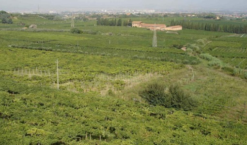
BACCHUS-DOC
The BACCHUS-DOC Radar and Optical Campaign was an area mapping project of vineyards near Frascati (Italy). ESA required high resolution geo-referenced airborne SAR data of different wavelength and polarisation (preferably polarimetric).