- All Categories (202)
- Data (39)
- News (86)
- Missions (9)
- Events (27)
- Tools (7)
- Campaigns (22)
- Documents (12)
DATA
Discover and download the Earth observation data you need from the broad catalogue of missions the European Space Agency operate and support.
Data - EO Sign In Authentication (Open)
Sea Ice Thematic Data Product [ALT_TDP_SI]
This is the Sea Ice Thematic Data Product (TDP) V1 resulting from the ESA FDR4ALT project and containing the sea ice related geophysical parameters, along with associated uncertainties: snow depth, radar and sea-ice freeboard, sea ice thickness and concentration. The collection covers data for the ERS-1, ERS-2 and Envisat missions, and bases on Level 1 data coming from previous reprocessing (ERS REAPER and the Envisat V3.0) but taking into account the improvements made at Level 0/Level 1 in the frame of FDR4ALT (ALT FDR). The Sea Ice TDP provides data from the northern or southern hemisphere in two files corresponding to the Arctic and Antarctic regions respectively for the winter periods only, i.e., October to June for the Arctic, and May to November for the Antarctic. For many aspects, the Sea Ice TDP is very innovative: First time series of sea-ice thickness estimates for ERS Homogeneous calibration, allowing the first Arctic radar freeboard time series from ERS-1 (1991) to CryoSat-2 (2021) Uncertainties estimated along-track with a bottom-up approach based on dominant sources ERS pulse blurring error corrected using literature procedure [Peacock, 2004] The FDR4ALT products are available in NetCDF format. Free standard tools for reading NetCDF data can be used. Information for expert altimetry users is also available in a dedicated NetCDF group within the products. Please consult the FDR4ALT Product User Guide before using the data. The FDR4ALT datasets represent the new reference data for the ERS/Envisat altimetry missions, superseding any previous mission data. Users are strongly encouraged to make use of these datasets for optimal results.
Data - Sample Data (Open)

CryoSat Data Samples
Download CryoSat data samples from Baseline-B, C, and D products.
Data - EO Sign In Authentication (Open)
MOS-1/1B ESA Orthorectified Map-oriented Products [MES_GEC_1P]
The ESA Orthorectified Map-oriented (Level 1) Products collection is composed of MOS-1/1B MESSR (Multi-spectral Electronic Self-Scanning Radiometer) data products generated as part of the MOS Bulk Processing Campaign using the MOS Processor v3.02. The products are available in GeoTIFF format and disseminated within EO-SIP packaging. Please refer to the MOS Product Format Specification for further details. The collection consists of data products of the following type: MES_GEC_1P: Geocoded Ellipsoid GCP Corrected Level 1 MOS-1/1B MESSR products which are the default products generated by the MOS MESSR processor in all cases (where possible), with usage of the latest set of Landsat improved GCP (Ground Control Points). These are orthorectified map-oriented products, corresponding to the old MOS-1/1B MES_ORT_1P products with geolocation improvements. MESSR Instrument Characteristics Band Wavelength Range (nm) Spatial Resolution (m) Swath Width (km) 1 (VIS) 510 – 690 50 100 2 (VIS) 610 – 690 50 100 3 (NIR) 720 – 800 50 100 4 (NIR) 800 – 1100 50 100
Data - EO Sign In Authentication (Open)
MOS-1/1B ESA System Corrected Map-oriented Products [MES_GES_1P]
The ESA System Corrected Map-oriented (Level 1) Products collection is composed of MOS-1/1B MESSR (Multi-spectral Electronic Self-Scanning Radiometer) data products generated as part of the MOS Bulk Processing Campaign using the MOS Processor v3.02. The products are available in GeoTIFF format and disseminated within EO-SIP packaging. Please refer to the MOS Product Format Specification for further details. The collection consists of data products of the following type: MES_GES_1P: Geocoded Ellipsoid System Corrected Level 1 MOS-1/1B MESSR products as generated by the MOS MESSR processor where the generation of MES_GEC_1P products is not possible. These replace the old MES_SYC_1P products. MESSR Instrument Characteristics Band Wavelength Range (nm) Spatial Resolution (m) Swath Width (km) 1 (VIS) 510 – 690 50 100 2 (VIS) 610 – 690 50 100 3 (NIR) 720 – 800 50 100 4 (NIR) 800 – 1100 50 100
Data - EO Sign In Authentication (Open)
MOS-1/1B ESA System Corrected VTIR Products [VTI_SYC_1P]
The ESA System Corrected (Level 1) MOS-1/1B VTIR Products collection is composed of MOS-1/1B VTIR (Visible and Thermal Infrared Radiometer) data products generated as part of the MOS Bulk Processing Campaign using the MOS Processor v3.02. The products are available in GeoTIFF format and disseminated within EO-SIP packaging. Please refer to the MOS Product Format Specification for further details. The collection consists of data products of the following type: VTI_SYC_1P: System corrected Level 1 MOS-1/1B VTIR products in EO-SIP format. VTIR Instrument Characteristics Band Wavelength Range (µm) Spatial Resolution (km) Swath Width (km) 1 (VIS) 0.5 – 0.7 0.9 1500 2 (TIR) 6.0 – 7.0 2.7 1500 3 (TIR) 10.5 – 11.5 2.7 1500 4 (TIR) 11.5 – 12.5 2.7 1500
Data - Fast Registration with immediate access (Open)
TanSat AGCS and CAPI products
The Atmospheric Carbon-dioxide Grating Spectrometer (ACGS) instrument is pushbroom spectrometer operating in NIR and SWIR bands which allows the measuring of CO2 mole fraction. The available ACGS products have a temporal coverage between March 2017 and January 2020 (not all days included in the time frame): L1A DS: Sample Dark Calibration sample product L1A GL: Sample Glint Sample products L1A LS: Sample Lamp Calibration sample product L1A ND: Principal-Plane Nadir Sample product L1A ZS: Sample Z-Axis Solar Calibration Sample L1B CAL DS: Sample Dark Calibration product L1B CAL LS: Sample Lamp Calibration product L1B CAL ZS: Sample Z-Axis Solar Calibration product L1B SCI GL: Sample Glint Science product L1B SCI ND: Principal-Plane Nadir Science product. The Cloud Aerosol Polarization Imager (CAPI) is a pushbroom radiometer in VIS, NIR and SWIR bands for the observation of aerosols and clouds optical properties. The CAPI products are available in a time range from July 2019 and January 2020 (not all days included in the time frame): L1A ND: Principal-Plane Nadir product L1B ND 1000M: Principal-Plane Nadir products at 1000 m resolution (1375 nm, 1640 nm) L1B ND 250M: Principal-Plane Nadir products at 250 m resolution (380 nm, 670 nm, 870 nm) L1B ND GEOQK: Principal-Plane Nadir georeferenced at 250 m resolution L1B ND GEO1K: Principal-Plane Nadir georeferenced at 1000 m resolution L1B ND OBC: Principal-Plane Nadir on-board calibrator product L2 ND CLM: Principal-Plane Nadir cloud flag product.
Data - Data Description
Aeolus Level 2C assisted wind fields resulting from NWP (Numerical Weather Prediction) assimilation processing
The Level 2C wind product of the Aeolus mission provides ECMWF analysis horizontal wind vectors at the geolocations of assimilated L2B HLOS wind components. The L2C can therefore be described as an Aeolus-assisted horizontal wind vector product. The L2C is a distinct product, however the L2C and L2B share a common Earth Explorer file template, with the L2C being a superset of the L2B. The L2C consists of extra datasets appended to the L2B product with information which are relevant to the data assimilation of the L2B winds.
Data - EO Sign In Authentication (Open)
Aeolus L2A Aerosol/Cloud optical product
The Level 2A aerosol/cloud optical products of the Aeolus mission include: Geo-located consolidated backscatter and extinction profiles Backscatter-to-extinction coefficient LIDAR ratio, scene classification Heterogeneity index Attenuated backscatter signals. Resolution: Horizontal resolution of L2A optical properties at observation scale (~87 km); Exceptions are group properties (horizontal accumulation of measurements from ~3 km to ~87 km) and attenuated backscatters (~3 km). Note: The resolution of "groups" in the L2A can only go down to 5 measurements at the moment, i.e. ~15 km horizontal resolution. This could be configured to go to 1 measurement - Vertical resolution 250-2000 m (Defined by Range Bin Settings).
Data - Project Proposal (Restrained)
GHGSat archive and tasking
GHGSat data produce measures of vertical column densities of greenhouse gas emissions ((currently CH4, but eventually CO2), provided on a pre-defined area of 12 km x 12 km, from the full sensor field-of-view. GHGSat Catalogue and New Collect data are available in three different data types: Single Observation: a single observation of a scene. Monthly Monitoring: guaranteed 12 successful observations in a year over a given site (once per month or flexible best effort cadence depending on weather). Weekly Monitoring: guaranteed 52 successful observations in a year over a given site (once a week or flexible best effort cadence based on weather), to accommodate large & persistent monitoring needs. Data are provided as an Emissions package containing the following products: Abundance dataset (Level 2): Set of per-pixel abundances in excess of the local background (ppb) for a single species, and per-pixel measurement error expressed as a standard deviation for a single site on a single satellite pass. Data format is 16-bit GeoTIFF. Concentration Maps (Level 2): High readability pseudocolour map combining surface reflectance, and column density expressed in ppb for a single species in PNG format. The relevant abundance dataset is provided as well. Emission Rates (Level 4): Instantaneous rate for a detected emission from a targeted source estimated using abundance datasets from a single satellite pass and applying dispersion modelling techniques. The delivered product includes the emission rate estimate with uncertainty and key dispersion parameters (in CSV format) as well as the abundance dataset used for the emission estimate. This product is only delivered in the Emissions package if an emission is detected within the abundance dataset. The Level 2 products will be delivered regardless of whether or not an emission is detected. The properties of available products are summarised in the table. Band(s) / Beam Mode(s) and Polarisation SWIR (1635-1675 nm), multiple bands, unpolarised Spatial Resolution <30 m Scene size 12 km x 12 km Species Measured CH4 Geometric Corrections Radial distortion, perspective projection Radiometric Corrections Detector pixel response, ghosting, spectral response, atmospheric correction including trace gas modelling and surface reflectance Details about the data provision, data access conditions and quota assignment procedure are described in the GHGSat Terms of Applicability.
Data - Fast Registration with approval (Restrained)
RADARSAT-2 ESA archive
The RADARSAT-2 ESA archive collection consists of RADARSAT-2 products requested by ESA supported projects over their areas of interest around the world. The dataset regularly grows as ESA collects new products over the years. Following Beam modes are available: Standard, Wide Swath, Fine Resolution, Extended Low Incidence, Extended High Incidence, ScanSAR Narrow and ScanSAR Wide. Standard Beam Mode allows imaging over a wide range of incidence angles with a set of image quality characteristics which provides a balance between fine resolution and wide coverage, and between spatial and radiometric resolutions. Standard Beam Mode operates with any one of eight beams, referred to as S1 to S8, in single and dual polarisation . The nominal incidence angle range covered by the full set of beams is 20 degrees (at the inner edge of S1) to 52 degrees (at the outer edge of S8). Each individual beam covers a nominal ground swath of 100 km within the total standard beam accessibility swath of more than 500 km. Beam Mode Product Nominal Resolution (metres) Nominal Pixel Spacing Range x Azimuth (metres) Resolution Range x Azimuth (metres) Nominal Scene Size Range x Azimuth (kilometres) Range of Angle of Incidence (degrees) Number of Looks Range x Azimuth Polarisations Options Standard SLC 25 8.0 or 11.8 x 5.1 9.0 or 13.5 x 7.7 100 x 100 20 - 52 1 x 1 Single Pol HH or VV or HV or VH - or - Dual HH + HV or VV + VH SGX 8.0 x 8.0 26.8 - 17.3 x 24.7 1 x 4 SGF 12.5 x 12.5 SSG, SPG Wide Swath Beam Mode allows imaging of wider swaths than Standard Beam Mode, but at the expense of slightly coarser spatial resolution. The three Wide Swath beams, W1, W2 and W3, provide coverage of swaths of approximately 170 km, 150 km and 130 km in width respectively, and collectively span a total incidence angle range from 20 degrees to 45 degrees. Polarisation can be single and dual. Beam Mode Product Nominal Resolution (metres) Nominal Pixel Spacing Range x Azimuth (metres) Resolution Range x Azimuth (metres) Nominal Scene Size Range x Azimuth (kilometres) Range of Angle of Incidence (degrees) Number of Looks Range x Azimuth Polarisations Options Wide SLC 30 11.8 x 5.1 13.5 x 7.7 150 x 150 20 - 45 1 x 1 Single: Pol HH or VV or HV or VH - or - Dual: HH + HV or VV + VH SGX 10 x 10 40.0 - 19.2 x 24.7 1 x 4 SGF 12.5 x 12.5 SSG, SPG Fine Resolution Beam Mode is intended for applications which require finer spatial resolution. Products from this beam mode have a nominal ground swath of 50 km. Nine Fine Resolution physical beams, F23 to F21, and F1 to F6 are available to cover the incidence angle range from 30 to 50 degrees. For each of these beams, the swath can optionally be centred with respect to the physical beam or it can be shifted slightly to the near or far range side. Thanks to these additional swath positioning choices, overlaps of more than 50% are provided between adjacent swaths. RADARSAT-2 can operate in single and dual polarisation for this beam mode. Beam Mode Product Nominal resolution (metres) Nominal Pixel Spacing Range x Azimuth (metres) Resolution Range x Azimuth (metres) Nominal Scene Size Range x Azimuth (kilometres) Range of Angle of Incidence (degrees) Number of Looks Range x Azimuth Polarisations Options Fine SLC 8 4.7 x 5.1 5.2 x 7.7 50 x 50 30 - 50 1 x 1 Single: Pol HH or VV or HV or VH - or - Dual: HH + HV or VV + VH SGX 3.13 x 3.13 10.4 - 6.8 x 7.7 1 x 1 SGF 6.25 x 6.25 SSG, SPG In the Extended Low Incidence Beam Mode, a single Extended Low Incidence Beam, EL1, is provided for imaging in the incidence angle range from 10 to 23 degrees with a nominal ground swath coverage of 170 km. Some minor degradation of image quality can be expected due to operation of the antenna beyond its optimum scan angle range. Only single polarisation is available. Beam Mode Product Nominal resolution (metres) Nominal Pixel Spacing Range x Azimuth (metres) Resolution Range x Azimuth (metres) Nominal Scene Size Range x Azimuth (kilometres) Range of Angle of Incidence (degrees) Number of Looks Range x Azimuth Polarisations Options Extended Low SLC 25 8.0 x 5.1 9.0 x 7.7 170 x 170 10 - 23 1 x 1 Single: HH SGX 10.0 x 10.0 52.7 - 23.3 x 24.7 1 x 4 SGF 12.5 x 12.5 SSG, SPG In the Extended High Incidence Beam Mode, six Extended High Incidence Beams, EH1 to EH6, are available for imaging in the 49 to 60 degree incidence angle range. Since these beams operate outside the optimum scan angle range of the SAR antenna, some degradation of image quality, becoming progressively more severe with increasing incidence angle, can be expected when compared with the Standard Beams. Swath widths are restricted to a nominal 80 km for the inner three beams, and 70 km for the outer beams. Only single polarisation available. Beam Mode Product Nominal resolution (metres) Nominal Pixel Spacing Range x Azimuth (metres) Resolution Range x Azimuth (metres) Nominal Scene Size Range x Azimuth (kilometres) Range of Angle of Incidence (degrees) Number of Looks Range x Azimuth Polarisations Options Extended High SLC 25 11.8 x 5.1 13.5 x 7.7 75 x 75 49 - 60 1 x 1 Single Pol HH SGX 8.0 x 8.0 18.2 - 15.9 x 24.7 1 x 4 SGF 12.5 x 12.5 SSG, SPG ScanSAR Narrow Beam Mode provides coverage of a ground swath approximately double the width of the Wide Swath Beam Mode swaths. Two swath positions with different combinations of physical beams can be used: SCNA, which uses physical beams W1 and W2, and SCNB, which uses physical beams W2, S5, and S6. Both options provide coverage of swath widths of about 300 km. The SCNA combination provides coverage over the incidence angle range from 20 to 39 degrees. The SCNB combination provides coverage over the incidence angle range 31 to 47 degrees. RADARSAT-2 can operate in single and dual polarisation for this beam mode. Beam Mode Product Nominal resolution (metres) Nominal Pixel Spacing Range x Azimuth (metres) Resolution Range x Azimuth (metres) Nominal Scene Size Range x Azimuth (kilometres) Range of Angle of Incidence (degrees) Number of Looks Range x Azimuth Polarisations Options ScanSAR Narrow SCN, SCF, SCS 20 25 x 25 81 - 38 x 40 - 70 300 x 300 20 - 46 2 x 2 Single Co or Cross: HH or VV or HV or VH - or - Dual: HH + HV or VV + VH ScanSAR Wide Beam Mode provides coverage of a ground swath approximately triple the width of the Wide Swath Beam Mode swaths. Two swath positions with different combinations of physical beams can be used: SCWA, which uses physical beams W1, W2, W3, and S7, and SCWB, which uses physical beams W1, W2, S5 and S6. The SCWA combination allows imaging of a swath of more than 500 km covering an incidence angle range of 20 to 49 degrees. The SCWB combination allows imaging of a swath of more than 450 km covering the incidence angle. Polarisation can be single and dual. Beam Mode Product Nominal resolution (metres) Nominal Pixel Spacing Range x Azimuth (metres) Resolution Range x Azimuth (metres) Nominal Scene Size Range x Azimuth (kilometres) Range of Angle of Incidence (degrees) Number of Looks Range x Azimuth Polarisations Options ScanSAR Wide SCW, SCF, SCS 100 50 x 50 163 - 73 x 78 - 106 500 x 500 20 - 49 4 x 2 Single Co or Cross: HH or VV or HV or VH - or - Dual: HH + HV or VV + VH These are the different products : SLC (Single Look Complex): Amplitude and phase information is preserved. Data is in slant range. Georeferenced and aligned with the satellite track SGF (Path Image): Data is converted to ground range and may be multi-look processed. Scene is oriented in direction of orbit path. Georeferenced and aligned with the satellite track. SGX (Path Image Plus): Same as SGF except processed with refined pixel spacing as needed to fully encompass the image data bandwidths. Georeferenced and aligned with the satellite track SSG(Map Image): Image is geocorrected to a map projection. SPG (Precision Map Image): Image is geocorrected to a map projection. Ground control points (GCP) are used to improve positional accuracy. SCN(ScanSAR Narrow)/SCF(ScanSAR Wide) : ScanSAR Narrow/Wide beam mode product with original processing options and metadata fields (for backwards compatibility only). Georeferenced and aligned with the satellite track SCF (ScanSAR Fine): ScanSAR product equivalent to SGF with additional processing options and metadata fields. Georeferenced and aligned with the satellite track SCS(ScanSAR Sampled) : Same as SCF except with finer sampling. Georeferenced and aligned with the satellite track. Spatial coverage: Check the spatial coverage of the collection on a map available on the Third Party Missions Dissemination Service.
Data - Announcement of Opportunity (Restrained)
Announcement of Opportunity for NoR
ESA invites submissions for the Network of Resources (NoR) call, which aims to support research, development and pre-commercial users to innovate their working practices, moving from a data download paradigm towards a 'bring the user to the data' paradigm.
Data - EO Sign In Authentication (Open)
SMOS - CryoSat L4 Sea Ice Thickness
The SMOS-CryoSat merged Sea Ice Thickness Level 4 product, in NetCDF format, is based on estimates from both the MIRAS and the SIRAL instruments with a significant reduction in the relative uncertainty for the thickness of the thin ice. A weekly averaged preliminary product is generated every day by the Alfred Wegener Institut (AWI) by merging the weekly CryoSat Sea Ice Thickness product and the daily SMOS Sea Ice Thickness retrieval. A final product is provided with a latency of about 3-4 weeks using a different global sea ice concentration product and a reprocessed CryoSat product. All grids are projected onto the 25 km EASE2 Grid based on a polar aspect spherical Lambert azimuthal equal-area projection. The grid dimension is 5400 x 5400 km, equal to a 432 x 432 grid centered on the geographic pole. Coverage is limited to the October-April (winter) period for the Northern Hemisphere, due to the melting season, from year 2010 onwards.
Data - EO Sign In Authentication (Open)
Aeolus Scientific L2B Rayleigh/Mie wind product
The Level 2B wind product of the Aeolus mission is a geo-located consolidated HLOS (horizontal line-of-sight) wind observation with actual atmospheric correction applied to Rayleigh channel. The product is generated within 3 hours after data acquisition.
Data - EO Sign In Authentication (Open)
Aeolus preliminary HLOS (horizontal line-of-sight) wind observations for Rayleigh and Mie receivers
The Level 1B wind product of the Aeolus mission contains the preliminary HLOS (horizontal line-of-sight) wind observations for Rayleigh and Mie receivers, which are generated in Near Real Time. Standard atmospheric correction (Rayleigh channel), receiver response and bias correction is applied. The product is generated within 3 hours after data acquisition.
Data - Campaigns (Open)
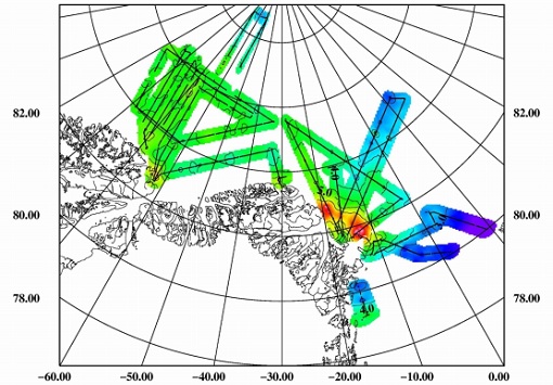
ESAG
The European Survey of Arctic Gravity (ESAG) campaign objective was to acquire measurements of the Arctic Ocean, in support of GOCE mission; and acquire scanning laser ranging data and profiling laser altimetry over sea-ice north of Greenland.
Data - External Data (Restrained)
SciSat-1: ACE-FTS and MAESTRO
SCISAT-1 data aim at monitoring and analysing the chemical processes that control the distribution of ozone in the upper troposphere and stratosphere. It provides acquisitions from the two instruments MAESTRO and ACE-FTS. MAESTRO: Measurement of Aerosol Extinction in the Stratosphere and Troposphere Retrieved by Occultation. Dual-channel optical spectrometer in the spectral region of 285-1030 nm. The objective is to measure ozone, nitrogen dioxide and aerosol/cloud extinction (solar occultation measurements of atmospheric attenuation during satellite sunrise and sunset with the primary objective of assessing the stratospheric ozone budget). Solar occultation spectra are being used for retrieving vertical profiles of temperature and pressure, aerosols, and trace gases (O3, NO2, H2O, OClO, and BrO) involved in middle atmosphere ozone distribution. The use of two overlapping spectrometers (280 - 550 nm, 500 - 1030 nm) improves the stray-light performance. The spectral resolution is about 1-2 nm. ACE-FTS: Fourier Transform Spectrometer. The objective is to measure the vertical distribution of atmospheric trace gases, in particular of the regional polar O3 budget, as well as pressure and temperature (derived from CO2 lines). The instrument is an adapted version of the classical sweeping Michelson interferometer, using an optimised optical layout. The ACE-FTS measurements are recorded every 2 s. This corresponds to a measurement spacing of 2-6 km which decreases at lower altitudes due to refraction. The typical altitude spacing changes with the orbital beta angle. For historical reasons, the retrieved results are interpolated onto a 1 km "grid" using a piecewise quadratic method. For ACE-FTS version 1.0, the results were reported only on the interpolated grid (every 1 km from 0.5 to 149.5 km). For versions 2.2, both the "retrieval" grid and the "1 km" grid profiles are available. SCISAT-1 collection provides ACE-FTS and MAESTRO Level 2 Data. As of today, ACE-FTS products are available in version 4.1, while MAESTRO products are available in version 3.13.
Data - Fast Registration with immediate access (Open)
Envisat SCIAMACHY Total column densities and stratospheric profiles [SCI_OL__2P]
The data product provides global column distributions and stratospheric profiles of various trace gases. Total column densities of O3, NO2, OClO, H2O, SO2, BrO, CO, HCHO, CHOCHO and CH4 are retrieved from Nadir measurements. Additional cloud parameters (fractional cloud coverage, cloud-top height, cloud optical thickness) and an aerosol absorption indicator are enclosed. Stratospheric profiles of O3, NO2, and BrO are derived from limb measurements and with flagging information for cloud-types. Tropospheric NO2 columns are retrieved combining limb and nadir measurements. The latest Level 2 dataset is Version 6.01.
Data - Fast Registration with immediate access (Open)
Envisat SCIAMACHY Geo-located atmospheric spectra [SCI_NL__1P]
This data product covers geo-located, radiometrically and spectrally calibrated limb and nadir radiance spectra for Nadir, Limb, and Occultation measurements with additional monitoring and calibration measurements. The Level 1b product is the lowest level of SCIAMACHY data delivered to the users. The instrument Instantaneous Field of View (IFoV) is approximately 0.045 deg (scan direction) x 1.8 deg (flight direction). This corresponds to a ground pixel size of 25 km x 0.6 km at the sub-satellite point (nadir) and of 103 km x 2.6 km at the Earth's horizon (limb). Nadir measurements have a maximum swath width of 960 km (in scan direction) and a typical footprint of 30 km (along track) x 60 km (across track). Limb measurements have a tangent height range spanning from 0 to 100 km with 3 km vertical resolution. Azimuth scans are performed for constant elevation angle, typically 34 elevation steps per limb scan. Maximum azimuth range is +/- 44 deg relative to S/C velocity (Note that the azimuth range is adjusted to observe the same atmospheric volume as for nadir measurements within five minutes). The radiometric resolution is 16 bits, with a spectral resolution of 0.24 nm to 1.5 nm, depending on the spectral range. The Sun normalized radiometric accuracy is 2 to 3% in unpolarized light, and 3 to 4% in polarized light. The relative radiometric accuracy is less than 1% and the spectral accuracy spans form 0.005 nm to 0.035 nm. Individual measurements from dedicated monitoring states include: Sun over diffuser Subsolar calibration Spectral lamp measurements White light source measurements Elevation mirror monitoring (Sun/Moon) ADC calibration Level 1b products are corrected for degradation applying a scan mirror model and m-factors. The latest Level 1b dataset is version 8.0X.
Data - EO Sign In Authentication (Open)
SMOS L3 Sea Ice Thickness
The SMOS Level 3 Sea Ice Thickness product, in NetCDF format, provides daily estimations of SMOS-retrieved sea ice thickness (and its uncertainty) at the edge of the Arctic Ocean during the October-April (winter) season, from year 2010 onwards. The sea ice thickness is retrieved from the SMOS L1C product, up to a depth of approximately 0.5-1 m, depending on the ice temperature and salinity. Daily maps, projected on polar stereographic grid of 12.5 km, are generated by the Alfred Wegener Institut (AWI). This product is complementary with sea ice thickness measurements from ESA's CryoSat and Copernicus Sentinel-3 missions.
Data - Project Proposal (Restrained)
RADARSAT-1 & 2 full archive and tasking
RADARSAT-1 products The Standard beam mode operates with any one of seven beam positions, referred to as S1 to S7. The nominal incidence angle range covered by the full set of Standard beams is from 20 degrees (at the inner edge of S1) to 49 degrees (at the outer edge of S7). Each individual beam covers a minimum ground swath of 100 km within the total 500 km accessibility swath of the full set of Standard beams. The nominal spatial resolution in the range direction is 26 m for S1 at near range to 20 m for S7 at far range. The nominal azimuth resolution is the same, 27 m, for all beam positions. The Wide beam modes are similar to the Standard beams except that the swath width achieved by this beam is 150 km rather than 100 km. As a result, only three Wide beams, W1, W2 and W3 are necessary to provide coverage of almost all of the 500 km swath range. They provide comparable resolution to the standard beam mode, though the increased ground swath coverage is obtained at the expense of a slight reduction in overall image quality. In the Fine beam mode the nominal azimuth resolution is 8.4 m, with range resolution 9.1 m to 7.8 m from F1 to F5. Since the radar operates with a higher sampling rate in this mode than in any of the other beam mode, the ground swath coverage has to be reduced to approximately 50 km in order to keep the downlink signal within its allocated bandwidth. Originally, five Fine beam positions, F1 to F5, were available to cover the far range of the swath with an incidence angle range from 37 to 47 degrees. By modifying timing parameters, 10 new positions have been added with offset ground coverage. Each original Fine beam position can either be shifted closer to or further away from Nadir. In Extended High beam mode six positions, EH1 to EH6, are available for collection of data in the 49 to 60 degree incidence angle range. Since this beam mode operates outside the optimum scan angle range of the SAR antenna, some minor degradation of image quality can be expected when compared with the Standard beam mode. Swath widths are restricted to a nominal 80 km for the inner three positions, and 70 km for the outer three positions. In Extended Low beam mode one position, EL1, is provided for imaging in the incidence angle range 10 to 23 degrees with nominal ground swath coverage of 170 km. As with the Extended High beam mode, some minor degradation of image quality can be expected due to operation of the antenna beyond its optimum elevation angle range. In ScanSAR mode, combinations of two, three or four single beams are used during data collection. Each beam is selected sequentially so that data is collected from a wider swath than possible with a single beam. The beam switching rates are chosen to ensure at least one "look" at the Earth's surface for each beam within the along track illumination time or dwell time of the antenna beam. In practice, the radar beam switching is adjusted to provide two looks per beam. The beam multiplexing inherent in ScanSAR operation reduces the effective sampling rate within each of the component beams; hence the increased swath coverage is obtained at the expense of spatial resolution. The ScanSAR Narrow mode combines two beams (incidence angle range of 20 to 39 degrees) or three beams (incidence angle from 31 to 46 degrees) and provides coverage of a nominal 300 km ground swath, with spatial resolution of 50 m. The ScanSAR Wide mode combines four beams, provides coverage of either 500 km (with incidence angle range of 20 to 49 degrees) or 450 km (incidence angle range from 20 to 46 degrees) nominal ground swaths depending on the beam combination. Beam Mode Product Ground coverage (km2) Nominal resolution (m) Polarisation ScanSAR wide SCW, SCF, SCS 500 x 500 100 Single and dual ScanSAR narrow SCN, SCF, SCS 300 x 300 60 Single and dual Wide SGF, SGX, SLC, SSG, SPG 150 x 150 24 Single and dual Standard SGF, SGX, SLC, SSG, SPG 100 x 100 24 Single Extended low SGF, SGX, SLC, SSG, SPG 170 x 170 24 Single Extended high SGF, SGX, SLC, SSG, SPG 75 x 75 24 Single Fine SGF, SGX, SLC, SSG, SPG 50 x 50 8 Single RADARSAT-2 products The Standard Beam Mode allows imaging over a wide range of incidence angles with a set of image quality characteristics which provides a balance between fine resolution and wide coverage, and between spatial and radiometric resolutions. Standard Beam Mode operates with any one of eight beams, referred to as S1 to S8. The nominal incidence angle range covered by the full set of beams is 20 degrees (at the inner edge of S1) to 52 degrees (at the outer edge of S8). Each individual beam covers a nominal ground swath of 100 km within the total standard beam accessibility swath of more than 500 km. The Wide Swath Beam Mode allows imaging of wider swaths than Standard Beam Mode, but at the expense of slightly coarser spatial resolution. The three Wide Swath beams, W1, W2 and W3, provide coverage of swaths of approximately 170 km, 150 km and 130 km in width respectively, and collectively span a total incidence angle range from 20 degrees to 45 degrees. The Fine Resolution Beam Mode is intended for applications which require finer spatial resolution. Products from this beam mode have a nominal ground swath of 50 km. Nine Fine Resolution physical beams, F23 to F21, and F1 to F6 are available to cover the incidence angle range from 30 to 50 degrees. For each of these beams, the swath can optionally be centred with respect to the physical beam or it can be shifted slightly to the near or far range side. Thanks to these additional swath positioning choices, overlaps of more than 50% are provided between adjacent swaths. In the Extended Low Incidence Beam Mode, a single Extended Low Incidence Beam, EL1, is provided for imaging in the incidence angle range from 10 to 23 degrees with a nominal ground swath coverage of 170 km. Some minor degradation of image quality can be expected due to operation of the antenna beyond its optimum scan angle range. In the Extended High Incidence Beam Mode, six Extended High Incidence Beams, EH1 to EH6, are available for imaging in the 49 to 60 degree incidence angle range. Since these beams operate outside the optimum scan angle range of the SAR antenna, some degradation of image quality, becoming progressively more severe with increasing incidence angle, can be expected when compared with the Standard Beams. Swath widths are restricted to a nominal 80 km for the inner three beams, and 70 km for the outer beams. ScanSAR Narrow Beam Mode provides coverage of a ground swath approximately double the width of the Wide Swath Beam Mode swaths. Two swath positions with different combinations of physical beams can be used: SCNA, which uses physical beams W1 and W2, and SCNB, which uses physical beams W2, S5, and S6. Both options provide coverage of swath widths of about 300 km. The SCNA combination provides coverage over the incidence angle range from 20 to 39 degrees. The SCNB combination provides coverage over the incidence angle range 31 to 47 degrees. ScanSAR Wide Beam Mode provides coverage of a ground swath approximately triple the width of the Wide Swath Beam Mode swaths. Two swath positions with different combinations of physical beams can be used: SCWA, which uses physical beams W1, W2, W3, and S7, and SCWB, which uses physical beams W1, W2, S5 and S6. The SCWA combination allows imaging of a swath of more than 500 km covering an incidence angle range of 20 to 49 degrees. The SCWB combination allows imaging of a swath of more than 450 km covering the incidence angle. In the Standard Quad Polarization Beam Mode, the radar transmits pulses alternately in horizontal (H) and vertical (V) polarisations, and receives the return signals from each pulse in both H and V polarisations separately but simultaneously. This beam mode therefore enables full polarimetric (HH+VV+HV+VH) image products to be generated. The Standard Quad Polarization Beam Mode operates with the same pulse bandwidths as the Standard Beam Mode. Products with swath widths of approximately 25 km can be obtained covering any area within the region from an incidence angle of 18 degrees to at least 49 degrees. The Wide Standard Quad Polarization Beam Mode operates the same way as the Standard Quad Polarization Beam Mode but with higher data acquisition rates, and offers wider swaths of approximately 50 km at equivalent spatial resolution. 21 beams are available covering any area from 18 degrees to 42 degrees, ensuring overlaps of about 50% between adjacent swaths. The Fine Quad Polarization Beam Mode provides full polarimetric imaging with the same spatial resolution as the Fine Resolution Beam Mode. Fine Quad Polarization Beam Mode products with swath widths of approximately 25 km can be obtained covering any area within the region from an incidence angle of 18 degrees to at least 49 degrees. The Wide Fine Quad Polarization Beam Mode operates the same way as the Fine Quad Polarization Beam Mode but with higher data acquisition rates, and offers a wider swath of approximately 50 km at equivalent spatial resolution. 21 beams are available covering any area from 18 degrees to 42 degrees, ensuring overlaps of about 50% between adjacent swaths. The Multi-Look Fine Resolution Beam Mode covers the same swaths as the Fine Resolution Beam Mode. Products with multiple looks in range and azimuth are generated at approximately the same spatial resolution as Fine Resolution Beam mode products, but with multiple looks and therefore improved radiometric resolution. Single look products are generated at finer spatial resolutions than Fine Resolution Beam Mode products. In order to obtain the multiple looks without a reduction in swath width, this beam mode operates with higher data acquisition rates and noise levels than Fine Resolution Beam Mode. As with the Fine Resolution Beam Mode, nine physical beams are available to cover the incidence angle range from 30 to 50 degrees, and additional near and/or far range swath positioning choices are available to provide additional overlap. The Wide Multi-Look Fine Resolution Beam Mode offers a wider coverage alternative to the regular Multi-Look Fine Beam Mode, while preserving the same spatial and radiometric resolution, but at the expense of higher data compression ratios (which leads to higher signal-dependent noise levels). The nominal swath width is 90 km compared to 50 km for the Multi-Look Fine Beam Mode. The nine physical beams are the same as in the Multi-Look Fine Beam Mode, covering incidence angles from approximately 30 to 50 degrees, but the additional near and far range swath positioning choices available in the Multi-Look Fine Beam Mode are not needed because the beam centered swaths are wide enough to overlap by more than 50%. The Ultra-Fine Resolution Beam Mode is intended for applications which require very high spatial resolution. The set of Ultra-Fine Resolution Beams cover any area within the incidence angle range from 20 to 50 degrees (soon to be extended to 54 degrees). Each beam within the set images a swath width of at least 20 km. The Wide Ultra-Fine Resolution Beam Mode provides the same spatial resolution as the Ultra-Fine mode as well as wider coverage, but at the expense of higher data compression ratios (which leads to higher signal-dependent noise levels). The set of Wide Ultra-Fine Resolution Beams cover any area within the incidence angle range from 30 to 50 degrees. Each beam within the set images a swath width of approximately 50 km. The Wide Fine Resolution Beam Mode is intended for applications which require both a finer spatial resolution and a wide swath. Products from this beam mode have a nominal ground swath equivalent to the ones offered by the Wide Swath Beam Mode (170 km, 150 km and 120 km) and a spatial resolution equivalent to the ones offered by the Fine Resolution Beam Mode, at the expense of somewhat higher noise levels. Three Wide Fine Resolution beam positions, F0W1 to F0W3 are available to cover the incidence angle range from 20 to 45 degrees. The Extra-Fine Resolution Beam Mode nominally provides similar swath width and incidence angle coverage as the Wide Fine Beam Mode, at even finer resolutions, but with higher data compression ratios and noise levels. The four Extra-Fine beams provide coverage of swaths of approximately 160 km, 124 km, 120 km and 108 km in width respectively, and collectively span a total incidence angle range from 22 to 49 degrees. This beam mode also offers additional optional processing parameter selections that allow for reduced-bandwidth single-look products, 4-look, and 28-look products. In Spotlight Beam Mode, the beam is steered electronically in order to dwell on the area of interest over longer aperture times, which allows products to be processed to finer azimuth resolution than in other modes. Unlike in other modes, Spotlight images are of fixed size in the along track direction. The set of Spotlight beams cover any area within the incidence angle range from 20 to 50 degrees (soon to be extended to 54 degrees). Each beam within the set images a swath width of at least 18 km. Beam Mode Product Nominal Pixel Spacing [Range x Azimuth] (metres) Nominal Resolution (metres) Resolution [Range x Azimuth] (metres) Nominal Scene Size [Range x Azimuth] (kilometres) Range of Angle of Incidence [Range] (degrees) Number of Looks [Range x Azimuth] Polarisations Options Spotlight SLC 1.3 x 0.4 <1 1.6 x 0.8 18 x 8 20 to 54 1 x 1 Single Co or Cross (HH or VV or HV or VH) SGX 1 or 0.8 x 1/3 4.6 - 2.0 x 0.8 SGF 0.5 x 0.5 SSG, SPG Ultra-fine SLC 1.3 x 2.1 3 1.6 x 2.8 20 x 20 20 to 54 1 x 1 Single Co or Cross (HH or VV or HV or VH) SGX 1 x 1 or 0.8 x 0.8 3.3 – 2.1 x 2.8 SGF 1.56 x 1.56 SSG, SPG Wide Ultra-fine SLC 1.3 x 2.1 3 3.1 x 4.6 50 x 50 29 to 50 1 x 1 Single Co or Cross (HH or VV or HV or VH) SGX 1 x 1 3.3 - 2.1 x 2.8 SGF 1.56 x 1.56 SSG, SPG Multi-look fine SLC 2.7 x 2.9 8 3.1 x 4.6 50 x 50 30 to 50 1 x 1 Single Co or Cross (HH or VV or HV or VH) SGX 3.13 x 3.13 10.4 - 6.8 x 7.6 2 x 2 SGF 6.25 x 6.25 SSG, SPG Wide Multi-look fine SLC 2.7 x 2.9 8 3.1 x 4.6 90 x 50 29 to 50 1 x 1 Single Co or Cross (HH or VV or HV or VH) SGX 3.13 x 3.13 10.8 - 6.8 x 7.6 2 x 2 SGF 6.25 x 6.25 SSG, SPG Extra-fine SLC (Full resolution) 2.7 x 2.9 5 3.1 x 4.6 125 x 125 22 to 49 1 x 1 Single Co or Cross (HH or VV or HV or VH) SLC (fine resolution) 4.3 x 5.8 5.2 x 7.6 SLC (standard resolution) 7.1 x 5.8 8.9 x 7.6 SLC (wide resolution) 10.6 x 5.8 13.3 x 7.6 SGX (1 look) 2.0 x 2.0 8.4 – 4.1 x 4.6 SGX (4 looks) 3.13 x 3.13 14 – 6.9 x 7.6 2 x 2 SGX (28 looks) 5.0 x 5.0 24 - 12 x 23.5 4 x 7 SGF (1 look) 3.13 x 3.13 8.4 - 4.1 x 4.6 1 x 1 SGF (4 looks) 6.25 x 6.25 14 - 6.9 x 7.6 2 x 2 SGF (28 looks) 8.0 x 8.0 24 - 12 x 23.5 4 x 7 SSG, SPG 3.13 x 3.13 8.4 - 4.1 x 4.6 1 x 1 Fine SLC 4.7 x 5.1 8 5.2 x 7.7 50 x 50 30 to 50 1 x 1 Single Co or Cross (HH or VV or HV or VH) or Dual (HH+HV or VV+VH) SGX 3.13 x 3.13 10.4 – 6.8 x 7.7 SGF 6.25 x 6.25 SSG, SPG Wide Fine SLC 4.7 x 5.1 8 5.2 x 7.7 150 x 150 20 to 45 1 x 1 Single Co or Cross (HH or VV or HV or VH) or Dual (HH+HV or VV+VH) SGX 3.13 x 3.13 14.9 - 7.3 x 7.7 SGF 6.25 x 6.25 SSG, SPG Standard SLC 8.0 or 11.8 x 5.1 25 9.0 or 13.5 x 7.7 100 x 100 20 - 52 1 x 1 Single Co or Cross (HH or VV or HV or VH) or Dual (HH+HV or VV+VH) SGX 8 x 8 26.8 - 17.3 x 24.7 1 x 4 SGF 12.5 x 12.5 SSG, SPG Wide SLC 11.8 x 5.1 30 13.5 x 7.7 150 x 150 20 - 45 1 x 1 Single Co or Cross (HH or VV or HV or VH) or Dual (HH+HV or VV+VH) SGX 10 x 10 40.0 - 19.2 x 24.7 1 x 4 SGF 12.5 x 12.5 SSG, SPG Extended High SLC 11.8 x 5.1 25 13.5 x 7.7 75 x 75 49 - 60 1 x 1 Single (HH only) SGX 8 x 8 18.2 - 15.9 x 24.7 1 x 4 SGF 12.5 x 12.5 SSG, SPG Extended Low SLC 8.0 x 5.1 25 9.0 x 7.7 170 x 170 10 - 23 1 x 1 Single (HH only) SGX 10 x 10 52.7 – 23.3 x 24.7 1 x 4 SGF 12.5 x 12.5 SSG, SPG Fine Quad-Pol SLC 4.7 x 5.1 8 5.2 x 7.6 25 x 25 18 - 49 1 x 1 Quad (HH+VV+HV+VH) SGX 3.13 x 3.13 16.5 – 6.8 x 7.6 1 x 1 SSG, SPG Wide Fine Quad-Pol SLC 4.7 x 5.1 8 5.2 x 7.6 50 x 25 18 - 42 1 x 1 Quad (HH+VV+HV+VH) SGX 3.13 x 3.13 17.3–7.8 x 7.6 SSG, SPG Standard Quad-Pol SLC 8 or 11.8 x 5.1 25 9.0 or 13.5 x 7.6 25 x 25 18 - 49 1 x 1 Quad (HH+VV+HV+VH) SGX 8 x 3.13 28.6 – 17.7 x 7.6 SSG, SPG Wide Standard Quad-Pol SLC 8 or 11.8 x 5.1 25 9.0 or 13.5 x 7.6 50 x 25 18 - 42 1 x 1 Quad (HH+VV+HV+VH) SGX 8 x 3.13 30.0 –16.7 x 7.6 SSG, SPG ScanSAR Narrow SCN, SCF, SCS 25 x 25 50 81–38 x 40-70 300 x 300 20 to 46 2 x 2 Single Co or Cross (HH or VV or HV or VH) or Dual (HH+HV or VV+VH) ScanSAR Wide SCW, SCF, SCS 50 x 50 100 163-73 x 78-106 500 x 500 20 to 49 4 x 2 Single Co or Cross (HH or VV or HV or VH) or Dual (HH+HV or VV+VH) These are the different products : SLC (Single Look Complex): Amplitude and phase information is preserved. Data is in slant range. Georeferenced and aligned with the satellite track SGF (Path Image): Data is converted to ground range and may be multi-look processed. Scene is oriented in direction of orbit path. Georeferenced and aligned with the satellite track. SGX (Path Image Plus): Same as SGF except processed with refined pixel spacing as needed to fully encompass the image data bandwidths. Georeferenced and aligned with the satellite track SSG (Map Image): Image is geocorrected to a map projection. SPG (Precision Map Image): Image is geocorrected to a map projection. Ground control points (GCP) are used to improve positional accuracy. SCN (ScanSAR Narrow)/SCF(ScanSAR Wide) : ScanSAR Narrow/Wide beam mode product with original processing options and metadata fields (for backwards compatibility only). Georeferenced and aligned with the satellite track SCF (ScanSAR Fine): ScanSAR product equivalent to SGF with additional processing options and metadata fields. Georeferenced and aligned with the satellite track SCS (ScanSAR Sampled) : Same as SCF except with finer sampling. Georeferenced and aligned with the satellite track.