- All Categories (593)
- Data (21)
- News (65)
- Missions (7)
- Events (35)
- Tools (22)
- Activities (10)
- Campaigns (6)
- Documents (427)
DATA
Discover and download the Earth observation data you need from the broad catalogue of missions the European Space Agency operate and support.
Data - EO Sign In Authentication (Open)
Landsat RBV
This dataset contains Landsat 3 Return Beam Vidicon (RBV) products, acquired by ESA by the Fucino ground station over its visibility mask. The data (673 scenes) are the result of the digitalization of the original 70 millimetre (mm) black and white film rolls. The RBV instrument was mounted on board the Landsat 1 to 3 satellites between 1972 and 1983, with 80 metre resolution. Three independent co-aligned television cameras, one for each spectral band (band 1: blue-green, band 2: yellow-red, band 3: NIR), constituted this instrument. The RBV system was redesigned for Landsat 3 to use two cameras operating in one broad spectral band (green to near-infrared; 0.505–0.750 µm), mounted side-by-side, with panchromatic spectral response and higher spatial resolution than on Landsat 1 and Landsat 2. Each of the cameras produced a swath of about 90 km (for a total swath of 180 km), with a spatial resolution of 40 m.
Data - Data Description
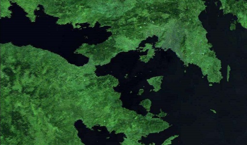
Landsat 7 ETM+ European and Mediterranean Countries Cloud Free Collection
This dataset contains the cloud-free products from Landsat 7 Enhanced Thematic Mapper collection acquired over Europe, North Africa and the Middle East; for each scene only one product is selected, with the minimal cloud coverage. The Landsat 7 ETM+ scenes typically cover 185 x 170 km. A standard full scene is nominally centred on the intersection between a Path and Row (the actual image centre can vary by up to 100 m). The data are system corrected.
Data - EO Sign In Authentication (Open)
Landsat 5 TM European and Mediterranean Countries Cloud Free Collection
This dataset contains the cloud-free products from Landsat 5 Thematic Mapper collection acquired over Europe, North Africa and the Middle East; for each scene only one product is selected, with the minimal cloud coverage. The acquired Landsat TM scene covers approximately 183 x 172.8 km. A standard full scene is nominally centred on the intersection between a path and row (the actual image centre can vary by up to 100 m). The data are system corrected.
Data - EO Sign In Authentication (Open)
Landsat 8 Collection 2 European Coverage
This dataset contains the European coverage of Landsat-8 Collection 2 data, both Level-1 and Level-2, acquired since the beginning of the mission. Landsat-8 Collection 2 is the result of a reprocessing effort on the archive and on newly acquired products with significant improvement with respect to Collection 1 on data quality, obtained by means of advancements in data processing and algorithm development. Primarily, this involves a relevant improvement in the absolute geolocation accuracy (now re-baselined to the European Space Agency Copernicus Sentinel-2 Global Reference Image (GRI) but also includes updated digital elevation modelling sources, improved Radiometric Calibration (even correction for the TIRS striping effect), enhanced Quality Assessment Bands, updated and consistent metadata files and usage of Cloud Optimised Georeferenced (COG) Tagged Image File Format. Landsat-8 Level-1 products combine data from the two Landsat instruments, OLI and TIRS. The Level-1 products generated can be either L1TP or L1GT: L1TP - Level-1 Precision Terrain (Corrected) (L1T) products: Radiometrically calibrated and orthorectified using ground control points (GCPs) and digital elevation model (DEM) data to correct for relief displacement. The highest quality Level-1 products suitable for pixel-level time series analysis. GCPs used for L1TP correction are derived from the Global Land Survey 2000 (GLS2000) data set. L1GT - Level-1 Systematic Terrain (Corrected) (L1GT) products: L1GT data products consist of Level-0 product data with systematic radiometric, geometric and terrain corrections applied and resampled for registration to a cartographic projection, referenced to the WGS84, G873, or current version. The dissemination server contains three different classes of Level-1 products Real Time (RT): Newly acquired Landsat-8 OLI/TIRS data are processed upon downlink but use an initial TIRS line-of-sight model parameters; the data are made available in less than 12 hours (4-6 hours typically). Once the data have been reprocessed with the refined TIRS parameters, the products are transitioned to either Tier 1 or Tier 2 and removed from the Real-Time tier (in 14-16 days). Tier 1 (T1): Landsat scenes with the highest available data quality are placed into Tier 1 and are considered suitable for time-series analysis. Tier 1 includes Level-1 Precision and Terrain (L1TP) corrected data that have well-characterized radiometry and are inter-calibrated across the different Landsat instruments. The georegistration of Tier 1 scenes is consistent and within prescribed image-to-image tolerances of ≦ 12-metre radial root mean square error (RMSE). Tier 2 (T2): Landsat scenes not meeting Tier 1 criteria during processing are assigned to Tier 2. Tier 2 scenes adhere to the same radiometric standard as Tier 1 scenes, but do not meet the Tier 1 geometry specification due to less accurate orbital information (specific to older Landsat sensors), significant cloud cover, insufficient ground control, or other factors. This includes Systematic Terrain (L1GT) and Systematic (L1GS) processed data. Landsat-8 Level-2 products are generated from L1GT and L1TP Level-1 products that meet the <76 degrees Solar Zenith Angle constraint and include the required auxiliary data inputs to generate a scientifically viable product. The data are available a couple of days after the Level-1 T1/T2. The Level-2 products generated can be L2SP or L2SR: L2SP - Level-2 Science Products (L2SP) products: include Surface Reflectance (SR), Surface Temperature (ST), ST intermediate bands, an angle coefficients file, and Quality Assessment (QA) Bands. L2SR - Level-2 Surface Reflectance (L2SR) products: include Surface Reflectance (SR), an angle coefficients file, and Quality Assessment (QA) Bands; it is generated if ST could not be generated. Two different categories of Level-1 products are offered: LC with Optical, Thermal and Quality Map images, LO with Optical and Quality Map images (Thermal not available). For the Level-2 data, only LC combined products are generated.
Data - EO Sign In Authentication (Open)
Landsat ETM+ ESA archive
This dataset contains all the Landsat-7 Enhanced Thematic Mapper high-quality ortho-rectified L1T products (or L1Gt where not enough GCPs are available) over Kiruna, Maspalomas, Matera and Neustrelitz visibility masks. The Landsat-7 ETM+ scenes typically covers 185 x 170 km. A standard full scene is nominally centred on the intersection between a Path and Row (the actual image centre can vary by up to 100 m). Each band requires 50 MB (uncompressed), and Band 8 requires 200 MB (panchromatic band with resolution of 15 m opposed to 30 m). Kiruna, Maspalomas and Matera Landsat-7 ETM density maps
Data - Data Description
Landsat TM ESA archive
This dataset contains all the Landsat-5 Thematic Mapper high-quality ortho-rectified L1T dataset acquired by ESA over the Fucino, Matera, Kiruna and Maspalomas visibility masks, as well as campaign data over Malindi, Bishkek, Chetumal, and Libreville. The acquired Landsat TM scene covers approximately 183 x 172.8 km. A standard full scene is nominally centred on the intersection between a path and row (the actual image centre can vary by up to 100 m). A full image is composed of 6920 pixels x 5760 lines and each band requires 40 MB of storage space (uncompressed) at 30 m spatial resolution in the VIS, NIR and SWIR as well as 120 m in the TIR spectral range. Kiruna Landsat TM GTC density map Maspalomas Landsat TM GTC density map Matera Landsat TM GTC density map
Data - Data Description
Landsat MSS ESA Archive
This dataset contains all the Landsat 1 to Landsat 5 Multi Spectral Scanner (MSS) high-quality ortho-rectified Level 1 GEO and GTC dataset acquired by ESA over the Fucino, Kiruna (active from April to September only) and Maspalomas (on campaign basis) visibility masks. The acquired Landsat MSS scene covers approximately 183 x 172.8 km. A standard full scene is nominally centred on the intersection between a path and row (the actual image centre can vary by up to 200 m). The altitude changed from 917 km to 705 km and therefore two World Reference Systems (WRS) were used. A full image is composed of 3460 pixels x 2880 lines with a pixel size of 60 m. Two different product levels are available: Geometrically and terrain corrected GTC Products (L1T): The most accurate level of processing as they incorporate Ground Control Points (GCPs) and a Digital Elevation Model (DEM) to provide systematic geometric and topographic accuracy; with geodetic accuracy dependent on the number, spatial distribution and accuracy of the GCPs over the scene extent, and the resolution of the DEM used. Geometrically corrected GEO Product (L1G): Normally generated where there is a lack of GCPs, and are derived purely from data collected by the sensor and spacecraft e.g. ephemeris data. Matera density and coverage map Kiruna density and coverage map Maspalomas density and coverage map
Data - Campaigns (Open)
ESAG
The European Survey of Arctic Gravity (ESAG) campaign objective was to acquire measurements of the Arctic Ocean, in support of GOCE mission; and acquire scanning laser ranging data and profiling laser altimetry over sea-ice north of Greenland.
Data - EO Sign In Authentication (Open)

VT GOCE Data
This collection contains the VT GOCE software and associated data set needed to run the software that is used for GOCE data visualisation.
Data - Project Proposal (Restrained)
RADARSAT-1 & 2 full archive and tasking
RADARSAT-1 products The Standard beam mode operates with any one of seven beam positions, referred to as S1 to S7. The nominal incidence angle range covered by the full set of Standard beams is from 20 degrees (at the inner edge of S1) to 49 degrees (at the outer edge of S7). Each individual beam covers a minimum ground swath of 100 km within the total 500 km accessibility swath of the full set of Standard beams. The nominal spatial resolution in the range direction is 26 m for S1 at near range to 20 m for S7 at far range. The nominal azimuth resolution is the same, 27 m, for all beam positions. The Wide beam modes are similar to the Standard beams except that the swath width achieved by this beam is 150 km rather than 100 km. As a result, only three Wide beams, W1, W2 and W3 are necessary to provide coverage of almost all of the 500 km swath range. They provide comparable resolution to the standard beam mode, though the increased ground swath coverage is obtained at the expense of a slight reduction in overall image quality. In the Fine beam mode the nominal azimuth resolution is 8.4 m, with range resolution 9.1 m to 7.8 m from F1 to F5. Since the radar operates with a higher sampling rate in this mode than in any of the other beam mode, the ground swath coverage has to be reduced to approximately 50 km in order to keep the downlink signal within its allocated bandwidth. Originally, five Fine beam positions, F1 to F5, were available to cover the far range of the swath with an incidence angle range from 37 to 47 degrees. By modifying timing parameters, 10 new positions have been added with offset ground coverage. Each original Fine beam position can either be shifted closer to or further away from Nadir. In Extended High beam mode six positions, EH1 to EH6, are available for collection of data in the 49 to 60 degree incidence angle range. Since this beam mode operates outside the optimum scan angle range of the SAR antenna, some minor degradation of image quality can be expected when compared with the Standard beam mode. Swath widths are restricted to a nominal 80 km for the inner three positions, and 70 km for the outer three positions. In Extended Low beam mode one position, EL1, is provided for imaging in the incidence angle range 10 to 23 degrees with nominal ground swath coverage of 170 km. As with the Extended High beam mode, some minor degradation of image quality can be expected due to operation of the antenna beyond its optimum elevation angle range. In ScanSAR mode, combinations of two, three or four single beams are used during data collection. Each beam is selected sequentially so that data is collected from a wider swath than possible with a single beam. The beam switching rates are chosen to ensure at least one "look" at the Earth's surface for each beam within the along track illumination time or dwell time of the antenna beam. In practice, the radar beam switching is adjusted to provide two looks per beam. The beam multiplexing inherent in ScanSAR operation reduces the effective sampling rate within each of the component beams; hence the increased swath coverage is obtained at the expense of spatial resolution. The ScanSAR Narrow mode combines two beams (incidence angle range of 20 to 39 degrees) or three beams (incidence angle from 31 to 46 degrees) and provides coverage of a nominal 300 km ground swath, with spatial resolution of 50 m. The ScanSAR Wide mode combines four beams, provides coverage of either 500 km (with incidence angle range of 20 to 49 degrees) or 450 km (incidence angle range from 20 to 46 degrees) nominal ground swaths depending on the beam combination. Beam Mode Product Ground coverage (km2) Nominal resolution (m) Polarisation ScanSAR wide SCW, SCF, SCS 500 x 500 100 Single and dual ScanSAR narrow SCN, SCF, SCS 300 x 300 60 Single and dual Wide SGF, SGX, SLC, SSG, SPG 150 x 150 24 Single and dual Standard SGF, SGX, SLC, SSG, SPG 100 x 100 24 Single Extended low SGF, SGX, SLC, SSG, SPG 170 x 170 24 Single Extended high SGF, SGX, SLC, SSG, SPG 75 x 75 24 Single Fine SGF, SGX, SLC, SSG, SPG 50 x 50 8 Single RADARSAT-2 products The Standard Beam Mode allows imaging over a wide range of incidence angles with a set of image quality characteristics which provides a balance between fine resolution and wide coverage, and between spatial and radiometric resolutions. Standard Beam Mode operates with any one of eight beams, referred to as S1 to S8. The nominal incidence angle range covered by the full set of beams is 20 degrees (at the inner edge of S1) to 52 degrees (at the outer edge of S8). Each individual beam covers a nominal ground swath of 100 km within the total standard beam accessibility swath of more than 500 km. The Wide Swath Beam Mode allows imaging of wider swaths than Standard Beam Mode, but at the expense of slightly coarser spatial resolution. The three Wide Swath beams, W1, W2 and W3, provide coverage of swaths of approximately 170 km, 150 km and 130 km in width respectively, and collectively span a total incidence angle range from 20 degrees to 45 degrees. The Fine Resolution Beam Mode is intended for applications which require finer spatial resolution. Products from this beam mode have a nominal ground swath of 50 km. Nine Fine Resolution physical beams, F23 to F21, and F1 to F6 are available to cover the incidence angle range from 30 to 50 degrees. For each of these beams, the swath can optionally be centred with respect to the physical beam or it can be shifted slightly to the near or far range side. Thanks to these additional swath positioning choices, overlaps of more than 50% are provided between adjacent swaths. In the Extended Low Incidence Beam Mode, a single Extended Low Incidence Beam, EL1, is provided for imaging in the incidence angle range from 10 to 23 degrees with a nominal ground swath coverage of 170 km. Some minor degradation of image quality can be expected due to operation of the antenna beyond its optimum scan angle range. In the Extended High Incidence Beam Mode, six Extended High Incidence Beams, EH1 to EH6, are available for imaging in the 49 to 60 degree incidence angle range. Since these beams operate outside the optimum scan angle range of the SAR antenna, some degradation of image quality, becoming progressively more severe with increasing incidence angle, can be expected when compared with the Standard Beams. Swath widths are restricted to a nominal 80 km for the inner three beams, and 70 km for the outer beams. ScanSAR Narrow Beam Mode provides coverage of a ground swath approximately double the width of the Wide Swath Beam Mode swaths. Two swath positions with different combinations of physical beams can be used: SCNA, which uses physical beams W1 and W2, and SCNB, which uses physical beams W2, S5, and S6. Both options provide coverage of swath widths of about 300 km. The SCNA combination provides coverage over the incidence angle range from 20 to 39 degrees. The SCNB combination provides coverage over the incidence angle range 31 to 47 degrees. ScanSAR Wide Beam Mode provides coverage of a ground swath approximately triple the width of the Wide Swath Beam Mode swaths. Two swath positions with different combinations of physical beams can be used: SCWA, which uses physical beams W1, W2, W3, and S7, and SCWB, which uses physical beams W1, W2, S5 and S6. The SCWA combination allows imaging of a swath of more than 500 km covering an incidence angle range of 20 to 49 degrees. The SCWB combination allows imaging of a swath of more than 450 km covering the incidence angle. In the Standard Quad Polarization Beam Mode, the radar transmits pulses alternately in horizontal (H) and vertical (V) polarisations, and receives the return signals from each pulse in both H and V polarisations separately but simultaneously. This beam mode therefore enables full polarimetric (HH+VV+HV+VH) image products to be generated. The Standard Quad Polarization Beam Mode operates with the same pulse bandwidths as the Standard Beam Mode. Products with swath widths of approximately 25 km can be obtained covering any area within the region from an incidence angle of 18 degrees to at least 49 degrees. The Wide Standard Quad Polarization Beam Mode operates the same way as the Standard Quad Polarization Beam Mode but with higher data acquisition rates, and offers wider swaths of approximately 50 km at equivalent spatial resolution. 21 beams are available covering any area from 18 degrees to 42 degrees, ensuring overlaps of about 50% between adjacent swaths. The Fine Quad Polarization Beam Mode provides full polarimetric imaging with the same spatial resolution as the Fine Resolution Beam Mode. Fine Quad Polarization Beam Mode products with swath widths of approximately 25 km can be obtained covering any area within the region from an incidence angle of 18 degrees to at least 49 degrees. The Wide Fine Quad Polarization Beam Mode operates the same way as the Fine Quad Polarization Beam Mode but with higher data acquisition rates, and offers a wider swath of approximately 50 km at equivalent spatial resolution. 21 beams are available covering any area from 18 degrees to 42 degrees, ensuring overlaps of about 50% between adjacent swaths. The Multi-Look Fine Resolution Beam Mode covers the same swaths as the Fine Resolution Beam Mode. Products with multiple looks in range and azimuth are generated at approximately the same spatial resolution as Fine Resolution Beam mode products, but with multiple looks and therefore improved radiometric resolution. Single look products are generated at finer spatial resolutions than Fine Resolution Beam Mode products. In order to obtain the multiple looks without a reduction in swath width, this beam mode operates with higher data acquisition rates and noise levels than Fine Resolution Beam Mode. As with the Fine Resolution Beam Mode, nine physical beams are available to cover the incidence angle range from 30 to 50 degrees, and additional near and/or far range swath positioning choices are available to provide additional overlap. The Wide Multi-Look Fine Resolution Beam Mode offers a wider coverage alternative to the regular Multi-Look Fine Beam Mode, while preserving the same spatial and radiometric resolution, but at the expense of higher data compression ratios (which leads to higher signal-dependent noise levels). The nominal swath width is 90 km compared to 50 km for the Multi-Look Fine Beam Mode. The nine physical beams are the same as in the Multi-Look Fine Beam Mode, covering incidence angles from approximately 30 to 50 degrees, but the additional near and far range swath positioning choices available in the Multi-Look Fine Beam Mode are not needed because the beam centered swaths are wide enough to overlap by more than 50%. The Ultra-Fine Resolution Beam Mode is intended for applications which require very high spatial resolution. The set of Ultra-Fine Resolution Beams cover any area within the incidence angle range from 20 to 50 degrees (soon to be extended to 54 degrees). Each beam within the set images a swath width of at least 20 km. The Wide Ultra-Fine Resolution Beam Mode provides the same spatial resolution as the Ultra-Fine mode as well as wider coverage, but at the expense of higher data compression ratios (which leads to higher signal-dependent noise levels). The set of Wide Ultra-Fine Resolution Beams cover any area within the incidence angle range from 30 to 50 degrees. Each beam within the set images a swath width of approximately 50 km. The Wide Fine Resolution Beam Mode is intended for applications which require both a finer spatial resolution and a wide swath. Products from this beam mode have a nominal ground swath equivalent to the ones offered by the Wide Swath Beam Mode (170 km, 150 km and 120 km) and a spatial resolution equivalent to the ones offered by the Fine Resolution Beam Mode, at the expense of somewhat higher noise levels. Three Wide Fine Resolution beam positions, F0W1 to F0W3 are available to cover the incidence angle range from 20 to 45 degrees. The Extra-Fine Resolution Beam Mode nominally provides similar swath width and incidence angle coverage as the Wide Fine Beam Mode, at even finer resolutions, but with higher data compression ratios and noise levels. The four Extra-Fine beams provide coverage of swaths of approximately 160 km, 124 km, 120 km and 108 km in width respectively, and collectively span a total incidence angle range from 22 to 49 degrees. This beam mode also offers additional optional processing parameter selections that allow for reduced-bandwidth single-look products, 4-look, and 28-look products. In Spotlight Beam Mode, the beam is steered electronically in order to dwell on the area of interest over longer aperture times, which allows products to be processed to finer azimuth resolution than in other modes. Unlike in other modes, Spotlight images are of fixed size in the along track direction. The set of Spotlight beams cover any area within the incidence angle range from 20 to 50 degrees (soon to be extended to 54 degrees). Each beam within the set images a swath width of at least 18 km. Beam Mode Product Nominal Pixel Spacing [Range x Azimuth] (metres) Nominal Resolution (metres) Resolution [Range x Azimuth] (metres) Nominal Scene Size [Range x Azimuth] (kilometres) Range of Angle of Incidence [Range] (degrees) Number of Looks [Range x Azimuth] Polarisations Options Spotlight SLC 1.3 x 0.4 <1 1.6 x 0.8 18 x 8 20 to 54 1 x 1 Single Co or Cross (HH or VV or HV or VH) SGX 1 or 0.8 x 1/3 4.6 - 2.0 x 0.8 SGF 0.5 x 0.5 SSG, SPG Ultra-fine SLC 1.3 x 2.1 3 1.6 x 2.8 20 x 20 20 to 54 1 x 1 Single Co or Cross (HH or VV or HV or VH) SGX 1 x 1 or 0.8 x 0.8 3.3 – 2.1 x 2.8 SGF 1.56 x 1.56 SSG, SPG Wide Ultra-fine SLC 1.3 x 2.1 3 3.1 x 4.6 50 x 50 29 to 50 1 x 1 Single Co or Cross (HH or VV or HV or VH) SGX 1 x 1 3.3 - 2.1 x 2.8 SGF 1.56 x 1.56 SSG, SPG Multi-look fine SLC 2.7 x 2.9 8 3.1 x 4.6 50 x 50 30 to 50 1 x 1 Single Co or Cross (HH or VV or HV or VH) SGX 3.13 x 3.13 10.4 - 6.8 x 7.6 2 x 2 SGF 6.25 x 6.25 SSG, SPG Wide Multi-look fine SLC 2.7 x 2.9 8 3.1 x 4.6 90 x 50 29 to 50 1 x 1 Single Co or Cross (HH or VV or HV or VH) SGX 3.13 x 3.13 10.8 - 6.8 x 7.6 2 x 2 SGF 6.25 x 6.25 SSG, SPG Extra-fine SLC (Full resolution) 2.7 x 2.9 5 3.1 x 4.6 125 x 125 22 to 49 1 x 1 Single Co or Cross (HH or VV or HV or VH) SLC (fine resolution) 4.3 x 5.8 5.2 x 7.6 SLC (standard resolution) 7.1 x 5.8 8.9 x 7.6 SLC (wide resolution) 10.6 x 5.8 13.3 x 7.6 SGX (1 look) 2.0 x 2.0 8.4 – 4.1 x 4.6 SGX (4 looks) 3.13 x 3.13 14 – 6.9 x 7.6 2 x 2 SGX (28 looks) 5.0 x 5.0 24 - 12 x 23.5 4 x 7 SGF (1 look) 3.13 x 3.13 8.4 - 4.1 x 4.6 1 x 1 SGF (4 looks) 6.25 x 6.25 14 - 6.9 x 7.6 2 x 2 SGF (28 looks) 8.0 x 8.0 24 - 12 x 23.5 4 x 7 SSG, SPG 3.13 x 3.13 8.4 - 4.1 x 4.6 1 x 1 Fine SLC 4.7 x 5.1 8 5.2 x 7.7 50 x 50 30 to 50 1 x 1 Single Co or Cross (HH or VV or HV or VH) or Dual (HH+HV or VV+VH) SGX 3.13 x 3.13 10.4 – 6.8 x 7.7 SGF 6.25 x 6.25 SSG, SPG Wide Fine SLC 4.7 x 5.1 8 5.2 x 7.7 150 x 150 20 to 45 1 x 1 Single Co or Cross (HH or VV or HV or VH) or Dual (HH+HV or VV+VH) SGX 3.13 x 3.13 14.9 - 7.3 x 7.7 SGF 6.25 x 6.25 SSG, SPG Standard SLC 8.0 or 11.8 x 5.1 25 9.0 or 13.5 x 7.7 100 x 100 20 - 52 1 x 1 Single Co or Cross (HH or VV or HV or VH) or Dual (HH+HV or VV+VH) SGX 8 x 8 26.8 - 17.3 x 24.7 1 x 4 SGF 12.5 x 12.5 SSG, SPG Wide SLC 11.8 x 5.1 30 13.5 x 7.7 150 x 150 20 - 45 1 x 1 Single Co or Cross (HH or VV or HV or VH) or Dual (HH+HV or VV+VH) SGX 10 x 10 40.0 - 19.2 x 24.7 1 x 4 SGF 12.5 x 12.5 SSG, SPG Extended High SLC 11.8 x 5.1 25 13.5 x 7.7 75 x 75 49 - 60 1 x 1 Single (HH only) SGX 8 x 8 18.2 - 15.9 x 24.7 1 x 4 SGF 12.5 x 12.5 SSG, SPG Extended Low SLC 8.0 x 5.1 25 9.0 x 7.7 170 x 170 10 - 23 1 x 1 Single (HH only) SGX 10 x 10 52.7 – 23.3 x 24.7 1 x 4 SGF 12.5 x 12.5 SSG, SPG Fine Quad-Pol SLC 4.7 x 5.1 8 5.2 x 7.6 25 x 25 18 - 49 1 x 1 Quad (HH+VV+HV+VH) SGX 3.13 x 3.13 16.5 – 6.8 x 7.6 1 x 1 SSG, SPG Wide Fine Quad-Pol SLC 4.7 x 5.1 8 5.2 x 7.6 50 x 25 18 - 42 1 x 1 Quad (HH+VV+HV+VH) SGX 3.13 x 3.13 17.3–7.8 x 7.6 SSG, SPG Standard Quad-Pol SLC 8 or 11.8 x 5.1 25 9.0 or 13.5 x 7.6 25 x 25 18 - 49 1 x 1 Quad (HH+VV+HV+VH) SGX 8 x 3.13 28.6 – 17.7 x 7.6 SSG, SPG Wide Standard Quad-Pol SLC 8 or 11.8 x 5.1 25 9.0 or 13.5 x 7.6 50 x 25 18 - 42 1 x 1 Quad (HH+VV+HV+VH) SGX 8 x 3.13 30.0 –16.7 x 7.6 SSG, SPG ScanSAR Narrow SCN, SCF, SCS 25 x 25 50 81–38 x 40-70 300 x 300 20 to 46 2 x 2 Single Co or Cross (HH or VV or HV or VH) or Dual (HH+HV or VV+VH) ScanSAR Wide SCW, SCF, SCS 50 x 50 100 163-73 x 78-106 500 x 500 20 to 49 4 x 2 Single Co or Cross (HH or VV or HV or VH) or Dual (HH+HV or VV+VH) These are the different products : SLC (Single Look Complex): Amplitude and phase information is preserved. Data is in slant range. Georeferenced and aligned with the satellite track SGF (Path Image): Data is converted to ground range and may be multi-look processed. Scene is oriented in direction of orbit path. Georeferenced and aligned with the satellite track. SGX (Path Image Plus): Same as SGF except processed with refined pixel spacing as needed to fully encompass the image data bandwidths. Georeferenced and aligned with the satellite track SSG (Map Image): Image is geocorrected to a map projection. SPG (Precision Map Image): Image is geocorrected to a map projection. Ground control points (GCP) are used to improve positional accuracy. SCN (ScanSAR Narrow)/SCF(ScanSAR Wide) : ScanSAR Narrow/Wide beam mode product with original processing options and metadata fields (for backwards compatibility only). Georeferenced and aligned with the satellite track SCF (ScanSAR Fine): ScanSAR product equivalent to SGF with additional processing options and metadata fields. Georeferenced and aligned with the satellite track SCS (ScanSAR Sampled) : Same as SCF except with finer sampling. Georeferenced and aligned with the satellite track.
Data - EO Sign In Authentication (Open)

GOCE TEC and ROTI
GOCE total electron content (TEC) and rate of TEC index (ROTI) data.
Data - EO Sign In Authentication (Open)
GOCE Telemetry
This collection contains all GOCE platform and instruments telemetry. For details see the Packets Description file.
Data - EO Sign In Authentication (Open)
GOCE Thermosphere Data
Thermospheric density and crosswind data products derived from GOCE data. Latest baseline _0200. The GOCE+ Air Density and Wind Retrieval using GOCE Data project produced a dataset of thermospheric density and crosswind data products which were derived from ion thruster activation data from GOCE telemetry. The data was combined with the mission's accelerometer and star camera data products. The products provide data continuty and extend the accelerometer-derived thermosphere density data sets from the CHAMP and GRACE missions. The resulting density and wind observations are made available in the form of time series and grids. These data can be applied in investigations of solar-terrestrial physics, as well as for the improvement and validation of models used in space operations. Funded by ESA through the Support To Science Element (STSE) of ESA's Earth Observation Envelope Programme, supporting the science applications of ESA's Living Planet programme, the project was a partnership between TU Delft, CNES and Hypersonic Technology Göttingen. Dataset history Date Change Reason 18/04/2019 - Time series data v2.0, covering the whole mission - Updated data set user manual - New satellite geometry and aerodynamic model - New vertical wind field - New data for the deorbit phase, (GPS+ACC and GPS-only versions) Updated satellite models and additional data 14/07/2016 - Time series data v1.5, covering the whole mission - Updated data set user manual Removal of noisy data 31/07/2014 - Time series data v1.4, covering the whole mission - Gridded data, now including error estimates - Updated data set user manual; Updated validation report; Updated ATBD Full GOCE dataset available 28/09/2013 Version 1.3 density/winds timeseries and gridded data released. User manual updated to v1.3 Bug fix and other changes 04/09/2013 Version 1.2 density/winds timeseries and gridded data released, with user manual First public data release of thermospheric density/winds data
Data - EO Sign In Authentication (Open)

GOCE Level 1
This collection contains the GOCE L1b data of the gradiometer, the star trackers, the GPS receiver, the magnetometers, magnetotorquers and the DFACS data of each accelerometer of the gradiometer. EGG_NOM_1b: latest baseline _0202 SST_NOM_1b: latest baseline _000x (always take the highest number available) ACC_DFx_1b: latest baseline _0001 (x=1:6) MGM_GOx_1b: latest baseline _0001 (x=1:3) MTR_GOC_1b: latest baseline _0001 SST_RIN_1b: latest baseline _000x (always take the highest number available) STR_VC2_1b: latest baseline _000x (always take the highest number available) STR_VC3_1b: latest baseline _000x (always take the highest number available).
Data - EO Sign In Authentication (Open)
GOCE Level 2
This collection contains GOCE level 2 data: Gravity Gradients in the gradiometer reference frame (EGG_NOM_2), in the terrestrial reference frame (EGG_TRF_2), GPS receiver derived precise science orbits (SST_PSO_2) and the non-tidal time variable gravity field potential with respect to a mean value in terms of a spherical harmonic series determined from atmospheric and oceanic mass variations as well as from a GRACE monthly gravity field time series (SST_AUX_2). EGG_NOM_2_: latest baseline: _0203 EGG_TRF_2_: latest baseline _0101 SST_AUX_2_: latest baseline _0001 SST_PSO_2_: latest baseline _0201.
Data - EO Sign In Authentication (Open)
GOCE Global Gravity Field Models and Grids
This collection contains gravity gradient and gravity anomalies grids at ground level and at satellite height. In addition it contains the GOCE gravity field models (EGM_GOC_2, EGM_GCF_2) and their covariance matrices (EGM_GVC_2): GOCE Gravity solution GRIDS Gridded Gravity gradients and anomalies at ground level: GO_CONS_GRC_SPW_2__20091101T000000_20111231T235959_0001.TGZ GO_CONS_GRC_SPW_2__20091101T055147_20120731T222822_0001.TGZ GO_CONS_GRC_SPW_2__20091101T055226_20131020T033415_0002.TGZ GO_CONS_GRC_SPW_2__20091009T000000_20131021T000000_0201.TGZ. Latest baseline is: GO_CONS_GRC_SPW_2__20091009T000000_20131021T000000_0201.TGZ. Gridded Gravity gradients and anomalies at satellite height: GO_CONS_GRD_SPW_2__20091101T055147_20100630T180254_0001.TGZ GO_CONS_GRD_SPW_2__20091101T055147_20120731T222822_0001.TGZ GO_CONS_GRD_SPW_2__20091101T055226_20131020T033415_0002.TGZ GO_CONS_GRD_SPW_2__20091009T000000_20131021T000000_0201.TGZ. Latest baseline is: GO_CONS_GRD_SPW_2__20091009T000000_20131021T000000_0201.TGZ. As output from the ESA-funded GOCE+ GeoExplore project, GOCE gravity gradients were combined with heterogeneous other satellite gravity information to derive a combined set of gravity gradients complementing (near)-surface data sets spanning all together scales from global down to 5 km. The data is useful for various geophysical applications and demonstrate their utility to complement additional data sources (e.g., magnetic, seismic) to enhance geophysical modelling and exploration. The GOCE+ GeoExplore project is funded by ESA through the Support To Science Element (STSE) and was undertaken as a collaboration of the Deutsches Geodätisches Forschungsinstitut (DGFI), Munich, DE, the Christian-Albrechts-Universität zu Kiel, the Geological Survey of Norway (NGU), Trondheim, Norway, TNO, the Netherlands and the University of West Bohemia, Plzen, CZ. Read more about gravity gradients and how GOCE delivered them in this Nature article: Satellite gravity gradient grids for geophysics. View images of the GOCE original gravity gradients and gradients with topographic reduction grids. Available data GRIDS File Type Gridded data: full Gravity Gradients, at 225 km and 255 km with and without topographic correction GGG_225 Computed from GOCE/GRACE gradients lower orbit phase February 2010 - October 2013 GGG_255 Computed from GOCE/GRACE gradients nominal orbit phase February 2010 - October 2013 TGG_225 Gravity gradient grids from topography at fixed height of 225/255 km above ellipsoid given in LNOF (Local North Oriented Frame) TGG_225 Gravity gradient grids from topography at fixed height of 225/255 km above ellipsoid given in LNOF (Local North Oriented Frame) MAPS File Type Maps of Gravity Gradients with and without topographic corrections Vij_225km_Patch_n.jpg Maps of grids from lower orbit phase with and without topographic correction from ETOPO1 Along-orbit File Type Full Gravity Gradients, along-orbit, in GRF and TRF reference frames. A detailed description is provided in the data set user manual GGC_GRF Combined gradients from GRACE (long wavelengths) & GOCE (measurement band) in the GRF (Gradiometer Reference Frame) GGC_TRF Combined gradients from GRACE (long wavelengths) & GOCE (measurement band) rotated from GRF to TRF (Terrestrial Reference Frame: North, West, Up) Direct solution First Generation Product: GO_CONS_EGM_GOC_2__20091101T000000_20100110T235959_0002.TGZ Variance/Covariance matrix: GO_CONS_EGM_GVC_2__20091101T000000_20100110T235959_0002.TGZ Second Generation Product: GO_CONS_EGM_GOC_2__20091101T000000_20100630T235959_0002.TGZ Variance/Covariance matrix: GO_CONS_EGM_GVC_2__20091101T000000_20100630T235959_0001.TGZ Third Generation Product: GO_CONS_EGM_GOC_2__20091101T000000_20110419T235959_0001.TGZ Variance/Covariance matrix: GO_CONS_EGM_GVC_2__20091101T000000_20110419T235959_0001.TGZ Coefficients (ICGEM format): GO_CONS_EGM_GCF_2__20091101T000000_20110419T235959_0001.IDF Fourth Generation Product: GO_CONS_EGM_GOC_2__20091101T000000_20120801T060000_0001.TGZ Variance/Covariance matrix: GO_CONS_EGM_GVC_2__20091101T000000_20120801T060000_0002.TGZ Fifth Generation Product: GO_CONS_EGM_GOC_2__20091101T000000_20131020T235959_0002.TG Variance/Covariance matrix: GO_CONS_EGM_GVC_2__20091101T000000_20131020T235959_0001.TGZ Coefficients (ICGEM format): GO_CONS_EGM_GOC_2__20091101T000000_20131020T235959_0001.IDF Sixth Generation Product: GO_CONS_EGM_GOC_2__20091009T000000_20131020T235959_0201.TGZ Variance/Covariance matrix: GO_CONS_EGM_GVC_2__20091009T000000_20131020T235959_0201.TGZ Coefficients (ICGEM format): GO_CONS_EGM_GOC_2__20091009T000000_20131020T235959_0201.IDF Release 6 gravity model validation report. Time-Wise solution First Generation Product: GO_CONS_EGM_GOC_2__20091101T000000_20100111T000000_0002.TGZ Variance/Covariance matrix: GO_CONS_EGM_GVC_2__20091101T000000_20100111T000000_0002.TGZ Second Generation Product: GO_CONS_EGM_GOC_2__20091101T000000_20100705T235500_0002.TGZ Variance/Covariance matrix: GO_CONS_EGM_GVC_2__20091101T000000_20100705T235500_0001.TGZ Third Generation Product: GO_CONS_EGM_GOC_2__20091101T000000_20110430T235959_0001.TGZ Variance/Covariance matrix: GO_CONS_EGM_GVC_2__20091101T000000_20110430T235959_0001.TGZ Coefficients (ICGEM format): GO_CONS_EGM_GCF_2__20091101T000000_20110430T235959_0001.IDF Fourth Generation Product: GO_CONS_EGM_GOC_2__20091101T000000_20120618T235959_0002.TGZ Variance/Covariance matrix: GO_CONS_EGM_GVC_2__20091101T000000_20120618T235959_0001.TGZ Fifth Generation Product: GO_CONS_EGM_GOC_2__20091101T000000_20131021T000000_0002.TGZ Variance/Covariance matrix: GO_CONS_EGM_GVC_2__20091101T000000_20131021T000000_0001.TGZ Coefficients (ICGEM format): GO_CONS_EGM_GOC_2__20091101T000000_20131021T000000_0001.IDF Sixth Generation Product: GO_CONS_EGM_GOC_2__20091009T000000_20131021T000000_0201.TGZ Variance/Covariance matrix: GO_CONS_EGM_GVC_2__20091009T000000_20131021T000000_0202.TGZ Coefficients (ICGEM format): GO_CONS_EGM_GOC_2__20091009T000000_20131021T000000_0201.IDF Combined gravity field GOCE model plus Antarctic and Arctic data (ICGEM format): GO_CONS_EGM_GOC_2__20091009T000000_20160119T235959_0201.IDF Download release 6 gravity model validation report.
Data - Campaigns (Open)
THERMOPOLIS
The THERMOPOLIS 2009 campaign mainly served the DUE “Urban Heat islands (UHI) and Urban Thermography (UT) Project”
Data - Campaigns (Open)
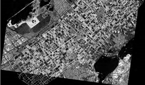
AgriSAR 2009
The AgriSAR 2009 campaign was defined to leverage the RADARSAT-2 mission to better understand and demonstrate the potential for GMES land monitoring user services, particularly in agriculture.
Data - Campaigns (Open)
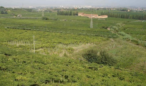
BACCHUS-DOC
The BACCHUS-DOC Radar and Optical Campaign was an area mapping project of vineyards near Frascati (Italy). ESA required high resolution geo-referenced airborne SAR data of different wavelength and polarisation (preferably polarimetric).
Data - Campaigns (Open)
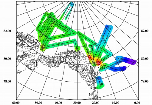
PolarGap
The primary objective of the PolarGap campaign was to carry out an airborne gravity survey covering the southern polar gap of the gravity field mission GOCE, beyond the coverage of the GOCE orbit.