EGG Overview
Design
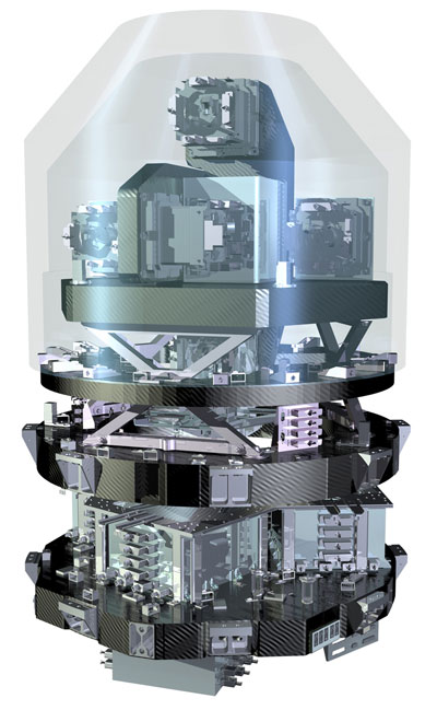
Gradiometers measure the rate of change of the gravity vector in all three perpendicular directions giving rise to a 'gravity gradient tensor' (GGT). The main objective of EGG was to measure the three components of the GGT.
It was the difference between the gravity measured by each sensor pair (along the axis of each of the three arms) that was used to calculate the gravity gradient. The gradiometer's panels on which the accelerometers are mounted consisted of a specific arrangement of carbon fibre layers that exhibit identical properties in all directions. These carbon fibres were embedded into a carbon matrix and assembled into skins that sandwich a carbon honeycomb. The end result was an integral carbon construction known as 'carbon-carbon'.
The principle of operation of the EGG was based on the measurement of the electric field needed to maintain a proof mass at the center of a cage. A six degree of freedom servo-controlled electrostatic suspension provides control of the proof mass in terms of translation and rotation. A pair of identical accelerometers, mounted on the ultra-stable structure, 50 cm apart, formed a "gradiometer arm." The difference measured between accelerations measured by each pair of the accelerometers, in the direction joining them, was the basic gradiometric datum (differential measurement).
Three identical arms were mounted orthogonally to one another and, the axes so defined are nominally aligned to the along-track, cross-track and vertical directions. The three differential accelerations provided direct, independent measurements: not only of the diagonal gravity components, but also of the perturbing linear and angular accelerations.
The overall chain functionality was obtained by integration of the following functions:
- The sensing function of the accelerometer was implemented in the Accelerometer Sensor Head (ASH). It was based on the controlled electrostatic levitation of a Platinum-Rhodium proof mass (PM).
- The conditioning function was implemented in the FEEU (Front End Electronic Unit). It included sensors of the proof mass position, amplifiers for the control voltages to apply on electrodes, A/D and D/A converters.
- The processing function was implemented in the GAIEU (Gradiometer Accelerometer Interface Electronic Unit). This latter unit was running real-time, full-digital control loops for the accelerometers (a total of 6 x 8 control laws), but also failure detection and recovery software, house-keeping monitoring, and data filtering and conditioning for DFACS (on board) and Science (downloaded) data.
The GGT measurement requirements called for a total of six accelerometers and conditioning functions, processed by one processing function. The six accelerometers were situated around the centre of mass of the satellite.
| Mass: | 180 kg |
| Power: | 100 W |
| Distance between accelerometers: | 0.5 m |
| Bandwidth as AOCS sensor: | DC to 5 Hz |
| Gravity measurement bandwidth: | 5 mHz to 100 mHz |
| Accelerometer Sensitivity: | 2x10–12 m/s2 vHz |
| Structure stability: | 0.2 ppm/K |
| Temperature stability: | 0.01°C over 200 |
Instrument Concept
An advanced gravity mission such as GOCE requires that the satellite and the system of sensor and control elements form one 'gravity-measuring device'; this is because the satellite itself also acted as a prime sensor. In contrast to most remote-sensing missions, there was virtually no division between the satellite and the instruments. The GOCE concept was unique in meeting four fundamental criteria for a high-resolution and high-accuracy gravity-field mission:
- Uninterrupted tracking in three spatial dimensions
- Continuous compensation for the effect of non-gravitational forces such as air-drag and radiation pressure
- Selection of a low orbital attitude for a strong gravity signal
- Counteraction of the gravity-field attenuation at altitude by employing satellite gravity gradiometry
From a scientific standpoint, these are the building blocks of the GOCE mission. In general, the lower the orbit and the higher the gravity signal, the more demanding are the requirements on all subsystems, as well as on the structure of the satellite and on the choice of materials. In turn, these building blocks dictate the choice of a related set of technical solutions for the instruments, sensors and actuators:
- An onboard GPS receiver used as a Satellite-to-Satellite Tracking Instrument (SSTI)
- A compensation system for all non-gravitational forces acting on the spacecraft, including a very sophisticated propulsion system
- The Electrostatic Gravity Gradiometer (EGG) - the main instrument
The principle of operation of the gradiometer relies on measuring the forces that maintain a 'proof mass' at the centre of a specially engineered 'cage'. Servo-controlled electrostatic suspension provides control of the proof mass in terms of linear and rotational motion. Three pairs of identical accelerometers, which form three 'gradiometer arms', are mounted on the ultra-stable structure. The difference between accelerations measured by each of two accelerometers (which are about 50 cm apart), in the direction joining them, is the basic gradiometric datum. The average of the two accelerations is proportional to the externally induced drag acceleration (common mode measurement). The three arms are mounted orthogonal to one another: one aligned with the satellite's trajectory, one perpendicular to the trajectory, and one pointing approximately towards the centre of Earth. By combining the differential accelerations, it is possible to derive the gravity-gradient components as well as the perturbing angular accelerations.