ALADIN Overview
Design
The ALADIN instrument (Atmospheric LAser Doppler INstrument) was a direct detection Doppler Wind Lidar operated in the ultra-violet region. It consisted of three major elements:
- A laser transmitter
- A combined Mie and Rayleigh backscattering receiver assembly
- A Cassegrain telescope with a 1.5 metres diameter.
The laser transmitter architecture was based on a pulsed diode-pumped Nd:YAG laser, frequency-tripled to provide 80 mJ pulses of ultraviolet light at 355 nm. This frequency was chosen because of the increased Rayleigh scattering in the ultraviolet region of the spectrum, and because it was eye-safe at distances greater than several hundred metres.
The laser was a complex system of laser sources and amplifiers, which were all packaged closely together. There were two small lasers to fix the frequency of the emitted pulses, a laser oscillator to generate pulses, two amplifier stages that boosted the energy of the light pulses to the required value and a frequency conversion crystals stage to produce the correct wavelength.
ALADIN had a very large telescope, which was used to collect the backscattered light from the atmosphere and then directed it to the receiver. Although large, it was made of lightweight ceramic material so it weighed only 55 kg.
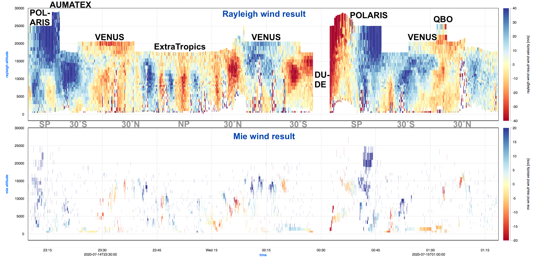
The processing of the backscatter signals produced line-of-sight wind-component profiles above thick clouds or down to the surface in clear air along the satellite track, every 10 (particle and cloud backscatter winds) to 87 (clear air backscatter winds) kilometres. Aeolus was also providing information about the vertical distribution of atmospheric cloud and particle (aerosol) layers. The data were provided to users in near-real-time (within three hours of sensing), and the wind product was used in operational weather forecasts by centres across the world.
Highly sensitive photo-detectors then transformed the light signals into electronic signals. The wind profiles were accumulated over at least 20 individual measurements before being downlinked to Earth for further averaging.
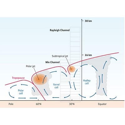
The Mie receiver consisted of a Fizeau interferometer with a resolution of 100 MHz (equivalent to 18 m/s). The received backscatter signal produced a linear fringe whose position was directly linked to the wind velocity; the wind speed was determined by the fringe centroid position to better than a tenth of the resolution (1.8 m/s).
The Rayleigh receiver employed a dual-filter Fabry–Pérot interferometer with a 2 GHz resolution and 5 GHz spacing. It analysed the wings of the Rayleigh spectrum with a CCD; the etalon was split into two zones, which were imaged separately on the detector.
How Aeolus Measured
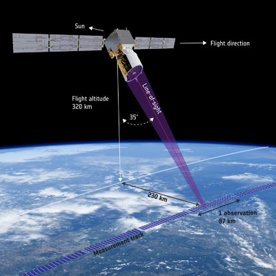
ALADIN measured the atmospheric wind by emitting short powerful pulses of ultraviolet light at a frequency of 50 Hz though its telescope down into the Earth's atmosphere. Between each pulse, the telescope collected the light that is backscattered from air molecules, aerosols and hydrometeors within the instrument field of view along its line-of-sight. The light was then directed to two receivers which measured the frequency of the backscattered light as a function of time. These recordings were then compared with the frequency of the emitted light pulses during the on-ground data processing. The movement of the air molecules and particles along the satellite view caused the frequency of the backscattered light to change with a tiny fraction due to the so-called Doppler effect. The Doppler effect occurs when an electromagnetic wave is emitted or reflected by a moving object. When the object is moving towards a target, the waves get compressed and hence result in a higher wave frequency. When it moves away, the waves get elongated and hence result in a lower wave frequency. This can for example be observed when an ambulance, emitting sound waves, is passing by.
Because ALADIN was performing time-gated differential frequency measurements, it was hence possible to determine the atmospheric wind at various altitudes above the surface from the its measurements. Aeolus measured the average (mostly east-west) wind component in 24 vertical layers for each channel, resulting in wind profiles every 250 m to 2 km from the surface up to about 30 km (lower stratosphere).
Aeolus Atmospheric Sampling – Range Bin Settings
The WIND Range Bin Settings (RBS) were defined based on latitude bands and small boxes (plot on the left); in each zone the atmosphere was sampled at different altitudes, as shown in the right plot.