- All Categories (29437)
- Data (111)
- News (166)
- Missions (31)
- Events (62)
- Tools (10)
- Activities (3)
- Campaigns (45)
- Documents (29009)
DATA
Discover and download the Earth observation data you need from the broad catalogue of missions the European Space Agency operate and support.
Data - EO Sign In Authentication (Open)
Land Ice Thematic Data Product [ALT_TDP_LI]
This is the Land Ice Thematic Data Product (TDP) V1 resulting from the ESA FDR4ALT project and containing estimates of ice sheet surface elevation and associated uncertainties. The collection covers data for three different missions: ERS-1, ERS-2 and Envisat, and based on Level 1 data coming from previous reprocessing (ERS REAPER and the Envisat V3.0) but taking into account the improvements made at Level 0/Level 1 in the frame of FDR4ALT (ALT FDR). The Land Ice TDP focuses specifically on the ice sheets of Greenland and Antarctica, providing these data in different files. For many aspects, the Land Ice Level 2 and Level 2+ processing is very innovative: Improved relocation approach correcting for topographic effects within the beam footprint to identify the Point of Closest Approach Homogeneous timeseries of surface elevation measurements at regular along-track reference nodes. The FDR4ALT products are available in NetCDF format. Free standard tools for reading NetCDF data can be used. Information for expert altimetry users is also available in a dedicated NetCDF group within the products. Please consult the FDR4ALT Product User Guide before using the data. The FDR4ALT datasets represent the new reference data for the ERS/Envisat altimetry missions, superseding any previous mission data. Users are strongly encouraged to make use of these datasets for optimal results.
Data - EO Sign In Authentication (Open)
Inland Waters Thematic Data Product [ALT_TDP_IW]
This is the Inland Waters Thematic Data Product (TDP) V1 resulting from the ESA FDR4ALT project and containing improved Water Surface Height (WSH) data record from the ERS-1, ERS-2 and Envisat missions estimated using the ICE1 retracking range for its better performance on the hydro targets. The FDR4ALT products are available in NetCDF format. Free standard tools for reading NetCDF data can be used. Information for expert altimetry users is also available in a dedicated NetCDF group within the products. Please consult the FDR4ALT Product User Guide before using the data. The FDR4ALT datasets represent the new reference data for the ERS/Envisat altimetry missions, superseding any previous mission data. Users are strongly encouraged to make use of these datasets for optimal results.
Data - Sample Data (Open)

CryoSat Data Samples
Download CryoSat data samples from Baseline-B, C, and D products.
Data - Sample Data (Open)
IRS-P6 (ResourceSat-1) Sample Data
Download free IRS-P6 (ResourceSat-1) sample datasets to preview products available for this mission.
Data - Announcement of Opportunity (Restrained)
Announcement of Opportunity for NovaSAR-1
ESA is launching an Announcement of Opportunity for the international scientific community to access data from the NovaSAR-1 mission for science and EO-based applications development.
Data - Project Proposal (Restrained)
NovaSAR-1 new tasking
NovaSAR-1 new acquisition data are available in two baseline acquisition modes: Stripmap – provides the highest resolution of 6 metres with up to 20 km swath selected from a 150 km field of regard, available in single polarisation. ScanSAR – has a 20 - 30 metre resolution and up to 150 km swath. Available in single polarisation. Within each of the baseline modes there are a variety of mode options that vary according to ground range resolution, incidence angles, swath width and the number of looks: Acquisition Mode Polarisation Resolution (m) Swath Width (km) Incidence Angles Number of Looks Stripmap Single: HH 6 20 16.0 – 25.38° 3 (1 range, 3 azimuth) 13 – 20 21.29 – 31.2° Single: VV 6 20 16.0 – 25.38° 3 (1 range, 3 azimuth) 13 – 20 21.29 – 31.2° ScanSAR Single: HH 20 100 15.0 - 24.66° 4 (2 range, 2 azimuth) 50 24.51 - 28.94° Single: VV 20 100 15.0 – 24.66° 4 (2 range, 2 azimuth) 50 24.51 - 28.94° Single: HH 30 150 11.29 – 25.93° 4 (2 range, 2 azimuth) 55 27.35 - 32.01° Single: VV 30 150 11.29 – 25.93° 4 (2 range, 2 azimuth) 55 27.35 - 32.01° NovaSAR-1 data are provided as a Level 2 (ARD) product as standard, but the accompanying Level 1 data may also be requested. Level 1 – delivered as reconstructed, unprocessed instrument data at full resolution. Level 2 (ARD) – delivered as a processed product with applied radiometric and geometric corrections i.e. orthorectification and spatial registration: Geocoded Ellipsoid Corrected (GEC) – Maritime and ocean applications Geocoded Terrain Corrected (GTC) – Land applications and change detection Where available, associated automatic identification system (AIS) data may be requested alongside the NovaSAR-1 data products.
Data - Fast Registration with immediate access (Open)
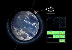
FSSCat products
The FSSCat collection provides hyperspectral data coverage over a number of locations around the world, as measured by the HyperScout 2 sensor. The FSSCat hyperspectral data products are comprised of 50 spectral bands, covering a spectral range of 450 – 950 nm with a spectral resolution of 18 nm (at FWHM). Imagery is available with an along-track ground sampling distance (GSD) of 75 m. To ensure a high degree of radiometric accuracy, HyperScout 2 data are validated through comparison with Sentinel-2 data products. The processing level of the data is L1C – calibrated top-of-atmosphere radiance, reflectance or brightness temperature. The raster type of the L1C data product is a GRID – a 2D or 3D raster where the (geo)location of the data is uniquely defined by the upper left pixel location of the raster and the pixel size of the raster, and the projection parameters of the raster (if georeferenced). The third dimension can e.g. be a spectral or third spatial dimension. The L-1C VNIR data product includes a hyperspectral cube of TOA reflectance in the VNIR range, as well as relevant meta-data that adheres to EDAP's best practice guidelines. This product consists of georeferenced and ortho-rectified image tiles that contain spectral reflectance data at the top-of-the-atmosphere. Each image tile contains radiometrically corrected and ortho-rectified band images that are projected onto a map, as well as geolocation information and the coordinate system used. Additionally, each image pixel provides TOA spectral reflectance data in scaled integers, conversion coefficients for spectral radiance units, viewing and solar zenith and azimuth angles, and quality flags.
Data - Announcement of Opportunity (Restrained)
Announcement of Opportunity for SAOCOM
In cooperation with CONAE (Comisión Nacional de Actividades Espaciales), ESA is launching an Announcement of Opportunity for the international scientific community to access data from the SAOCOM mission for science and EO-based applications development.
Data - Announcement of Opportunity (Restrained)

Announcement of Opportunity for S3VT (Sentinel-3 Validation Team)
In the framework of a Copernicus collaborative agreement ESA and EUMETSAT invite interested groups and individuals to support the Sentinel-3 Validation Team (S3VT).
Data - Fast Registration with approval (Restrained)
European Cities: Cartosat-1 Euro-Maps 3D
A large number of European cities are covered by this dataset; for each city you can find one or more Cartosat-1 ortho image products and one or more Euro-Maps 3D DSM tiles clipped to the extent of the ortho coverage. The Euro-Maps 3D DSM is a homogeneous, 5 m spaced Digital Surface Model semi-automatically derived from 2.5 m Cartosat-1 in-flight stereo data with a vertical accuracy of 10 m. The very detailed and accurate representation of the surface is achieved by using a sophisticated and well adapted algorithm implemented on the basis of the Semi-Global Matching approach. The final product includes several pixel-based quality and traceability layers: The dsm layer (*_dsm.tif) contains the elevation heights as a geocoded raster file The source layer (*_src.tif) contains information about the data source for each height value/pixel The number layer (*_num.tif) contains for each height value/pixel the number of IRS-P5 Cartosat-1 stereo pairs used for the generation of the DEM The quality layer (*_qc.tif) is set to 1 for each height/pixel value derived from IRS-P5 Cartosat-1 data and which meets or exceeds the product specifications The accuracy vertical layer (*_acv.tif) contains the absolute vertical accuracy for each quality controlled height value/pixel. The ortho image is a Panchromatic image at 2.5 m resolution. The following table defines the offered product types. EO-SIP product type Description PAN_PAM_3O IRS-P5 Cartosat-1 ortho image DSM_DEM_3D IRS-P5 Cartosat-1 DSM
Data - EO Sign In Authentication (Open)
PAZ ESA archive
The PAZ ESA archive collection consists of PAZ Level 1 data previously requested by ESA supported projects over their areas of interest around the world and, as a consequence, the products are scattered and dispersed worldwide and in different time windows. The dataset regularly grows as ESA collects new products over the years. Available modes are: StripMap mode (SM): SSD less than 3 m for a scene 30 km x 50 km in single polarization or 15 km x 50 km in dual polarisation ScanSAR mode (SC): the scene is 100 x 150 km2, SSD less than 18 m in signle pol only Wide ScanSAR mode (WS): single polarisation only, with SS less than 40 m and scene size of 270 x 200 km2 Spotlight modes (SL): SSD less than 2 m for a scene 10 km x 10 km, both single and dual polarization are available High Resolution Spotlight mode (HS): in both single and dual polarisation, the scene is 10x5 km2, SSD less than 1 m Staring Spotlight mode (ST): SSD is 25 cm, the scene size is 4 x 4 km2, in single polarisation only. The available geometric projections are: Single Look Slant Range Complex (SSC): single look product, no geocoding, no radiometric artifact included, the pixel spacing is equidistant in azimuth and in ground range Multi Look Ground Range Detected (MGD): detected multi look product, simple polynomial slant-to-ground projection is performed in range, no image rotation to a map coordinate system is performed Geocoded Ellipsoid Corrected (GEC): multi look detected product, projected and re-sampled to the WGS84 reference ellipsoid with no terrain corrections Enhanced Ellipsoid Corrected (EEC): multi look detected product, projected and re-sampled to the WGS84 reference ellipsoid, the image distortions caused by varying terrain height are corrected using a DEM. The following table summarises the offered product types. EO-SIP product type Operation Mode Geometric Projection Geometric Projection PSP_SM_SSC Stripmap (SM) Single Look Slant Range Complex (SSC) PSP_SM_MGD Stripmap (SM) Multi Look Ground Range Detected (MGD) PSP_SM_GEC Stripmap (SM) Geocoded Ellipsoid Corrected (GEC) PSP_SM_EEC Stripmap (SM) Enhanced Ellipsoid Corrected (EEC) PSP_SC_MGD ScanSAR (SC) Multi Look Ground Range Detected (MGD) PSP_SC_GEC ScanSAR (SC) Multi Look Ground Range Detected (MGD) PSP_SC_EEC ScanSAR (SC) Geocoded Ellipsoid Corrected (GEC) PSP_SC_SSC ScanSAR (SC) Enhanced Ellipsoid Corrected (EEC) PSP_SL_SSC Spotlight (SL) Single Look Slant Range Complex (SSC) PSP_SL_MGD Spotlight (SL) Multi Look Ground Range Detected (MGD) PSP_SL_GEC Spotlight (SL) Geocoded Ellipsoid Corrected (GEC) PSP_SL_EEC Spotlight (SL) Enhanced Ellipsoid Corrected (EEC) PSP_HS_SSC High Resolution Spotlight (HS) Single Look Slant Range Complex (SSC) PSP_HS_MGD High Resolution Spotlight (HS) Multi Look Ground Range Detected (MGD) PSP_HS_GEC High Resolution Spotlight (HS) Geocoded Ellipsoid Corrected (GEC) PSP_HS_EEC High Resolution Spotlight (HS) Enhanced Ellipsoid Corrected (EEC) PSP_ST_SSC Staring Spotlight (ST) Single Look Slant Range Complex (SSC) PSP_ST_MGD Staring Spotlight (ST) Multi Look Ground Range Detected (MGD) PSP_ST_GEC Staring Spotlight (ST) Geocoded Ellipsoid Corrected (GEC) PSP_ST_EEC Staring Spotlight (ST) Enhanced Ellipsoid Corrected (EEC) PSP_WS_SSC Wide ScanSAR (WS) Single Look Slant Range Complex (SSC) PSP_WS_MGD Wide ScanSAR (WS) Multi Look Ground Range Detected (MGD) PSP_WS_GEC Wide ScanSAR (WS) Geocoded Ellipsoid Corrected (GEC) PSP_WS_EEC Wide ScanSAR (WS) Enhanced Ellipsoid Corrected (EEC) As per ESA policy, very high-resolution data over conflict areas cannot be provided.
Data - Project Proposal (Restrained)
Vision-1 full archive and tasking
Vision-1 provides very high resolution optical products, with 87cm resolution in Panchromatic mode and 3.48m in Multispectral Mode. Products are in DIMAP format; the image is in GeoTiff format with 16 bit encoding; the applied geographical projection is WGS84 UTM. Spectral band combination options: Panchromatic (PAN): includes data contained within a single high resolution black and white band, with product pixel size of 0.87m Multispectral (MS4): includes four multispectral (colour) bands: Blue, Green, Red and Near Infrared. The product pixel size is 3.48m Bundle (BUN): provides both the 4-band multispectral, and the panchromatic data from the same acquisition in a single, non-merged product. Data is provided as 16-bit GeoTiffs with pixel sizes of 3.48m and 0.87m for MS and PAN data respectively Pansharpened (PSH): single higher resolution 0.87 colour product obtained by the combination of the visual coloured information of the multispectral data with the details provided in the panchromatic data. Two different geometric processing levels are: Projected (level 2): The product is mapped onto the Earth cartographic system using a standard reference datum and projection system at a constant terrestrial altitude, relative to the reference ellipsoid. By default, the map projection system is WGS84/UTM. The image is georeferenced without the application of a Digital Elevation Model (DEM) and supplied with the RPC model file. Pansharpened are not available as projected product Standard Ortho (level 3): georeferenced image in Earth geometry, including the application of a Airbus World DEM for Ortho and GCPs (using Airbus Intelligence One Atlas BaseMap as reference). The orthorectification procedure eliminates the perspective effect on the ground (excluding buildings) to restore the geometry of a vertical shot. Only the basic radiometric processing is available providing the radiance value. As per ESA policy, very high-resolution imagery of conflict areas cannot be provided.
Data - External Data (Restrained)
SAOCOM Europe data products
This collection provides access to the SAOCOM products acquired in the ASI Zone of Exclusivity, that correspond mainly to the European territory plus the international waters in front of North Africa and the Middle East, archived and catalogued in the ASI/CONAE dissemination system. ASI Zone of Exclusivity Platform SAOCOM 1A only (in future SAOCOM-1B will be added) Instrument L-Band SAR, 1.275 GHz Sensor mode STRIPMAP for data acquired at fixed azimuth steering (beam from S1 up to S10) TOPSAR for data acquired in ScanSAR like mode (Mode A, Mode B or Wide) Processing level L1A - SLC (single look complex, slat range), L1B - DI (detected image, ground range), L1C - GEC (geocoded on ellipsoid), L1D - GTC (geocoded on DEM) Resolution STRIPMAP: 10m TOPSAR Narrow: 30 - 50m TOPSAR WIDE: 50 - 100m Swath Width STRIPMAP: 20 - 40 km TOPSAR Narrow: 100 - 150 km TOPSAR Wide: 220 - 350 km Polarization Single polarization (HH or VV) only for STRIPMAP Double polarization (HHHV or VHVV) for both STRIPMAP and TOPSAR Quad Polarization for both STRIPMAP and TOPSAR
Data - Project Proposal (Restrained)
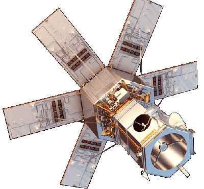
WorldView-4 Full Archive
WorldView-4 high resolution optical products are available as part of the Maxar Standard Satellite Imagery products from the QuickBird, WorldView-1/-2/-3/4, and GeoEye-1 satellites. All details about the data provision, data access conditions and quota assignment procedure are described into the Terms of Applicability available in Resources section. In particular, WorldView-4 offers archive panchromatic products up to 0.31 m GSD resolution, and 4-Bands Multispectral products up to 1.24 m GSD resolution. Band Combination Data Processing Level Resolution Panchromatic and 4-bands Standard (2A) / View Ready Standard (OR2A) 15 cm HD, 30 cm HD, 30 cm, 40 cm, 50/60 cm View Ready stereo 30 cm, 40 cm, 50/60 cm Map Ready (Ortho) 1:12.000 Orthorectified 15 cm HD, 30 cm HD, 30 cm, 40 cm, 50/60 cm The options for 4-Bands are the following: 4-Band Multispectral (BLUE, GREEN, RED, NIR1) 4-Band Pan-sharpened (BLUE, GREEN, RED, NIR1) 4-Band Bundle (PAN, BLUE, GREEN, RED, NIR1) 3-Bands Natural Colour (pan-sharpened BLUE, GREEN, RED) 3-Band Colored Infrared (pan-sharpened GREEN, RED, NIR1) Native 30 cm and 50/60 cm resolution products are processed with MAXAR HD Technology to generate respectively the 15 cm HD and 30 cm HD products: the initial special resolution (GSD) is unchanged but the HD technique increases the number of pixels and improves the visual clarity achieving aesthetically refined imagery with precise edges and well-reconstructed details.
Data - Fast Registration with approval (Restrained)
WorldView ESA archive
The WorldView ESA archive is composed of products acquired by WorldView-1, -2, -3 and -4 satellites and requested by ESA supported projects over their areas of interest around the world Panchromatic, 4-Bands, 8-Bands and SWIR products are part of the offer, with the resolution at Nadir depicted in the table. Band Combination Mission GSD Resolution at Nadir GSD Resolution (20° off nadir) Panchromatic WV-1 50 cm 55 cm WV-2 46 cm 52 cm WV-3 31 cm 34 cm WV-4 31 cm 34 cm 4-Bands WV-2 1.84 m 2.4 m WV-3 1.24 m 1.38 m WV-4 1.24 m 1.38 m 8-Bands WV-2 1.84 m 2.4 m WV-3 1.24 m 1.38 m SWIR WV-3 3.70 m 4.10 m The 4-Bands includes various options such as Multispectral (separate channel for Blue, Green, Red, NIR1), Pan-sharpened (Blue, Green, Red, NIR1), Bundle (separate bands for PAN, Blue, Green, Red, NIR1), Natural Colour (pan-sharpened Blue, Green, Red), Coloured Infrared (pan-sharpened Green, Red, NIR). The 8-Bands being an option from Multispectral (COASTAL, Blue, Green, Yellow, Red, Red EDGE, NIR1, NIR2) and Bundle (PAN, COASTAL, Blue, Green, Yellow, Red, Red EDGE, NIR1, NIR2). The processing levels are: Standard (2A): normalised for topographic relief View Ready Standard: ready for orthorectification (RPB files embedded) View Ready Stereo: collected in-track for stereo viewing and manipulation (not available for SWIR) Map Scale (Ortho) 1:12,000 Orthorectified: additional processing unnecessary Spatial coverage: Check the spatial coverage of the collection on a map available on the Third Party Missions Dissemination Service. The following table summarises the offered product types EO-SIP Product Type Band Combination Processing Level Missions WV6_PAN_2A Panchromatic (PAN) Standard/View Ready Standard WorldView-1 and 4 WV6_PAN_OR Panchromatic (PAN) View Ready Stereo WorldView-1 and 4 WV6_PAN_MP Panchromatic (PAN) Map Scale Ortho WorldView-1 and 4 WV1_PAN__2A Panchromatic (PAN) Standard/View Ready Standard WorldView-2 and 3 WV1_PAN__OR Panchromatic (PAN) View Ready Stereo WorldView-2 and 3 WV1_PAN__MP Panchromatic (PAN) Map Scale Ortho WorldView-2 and 3 WV1_4B__2A 4-Band (4B) Standard/View Ready Standard WorldView-2, 3 and 4 WV1_4B__OR 4-Band (4B) View Ready Stereo WorldView-2, 3 and 4 WV1_4B__MP 4-Band (4B) Map Scale Ortho WorldView-2, 3 and 4 WV1_8B_2A 8-Band (8B) Standard/View Ready Standard WorldView-2 and 3 WV1_8B_OR 8-Band (8B) View Ready Stereo WorldView-2 and 3 WV1_8B_MP 8-Band (8B) Map Scale Ortho WorldView-2 and 3 WV1_S8B__2A SWIR Standard/View Ready Standard WorldView-3 WV1_S8B__MP SWIR Map Scale Ortho WorldView-3 As per ESA policy, very high-resolution imagery of conflict areas cannot be provided.
Data - Data Description
Envisat ASAR AP Co- and Cross-polar L0 [ASA_APC/APH/APV_0P]
The ASAR Alternating Polarization Mode Level 0 (Co-polar and Cross-polar H and V) products contain time-ordered Annotated Instrument Source Packets (AISPs) corresponding to one of the three possible polarisation combinations: HH & HV, VV & VH and HH & VV, respectively. The echo samples in the AISPs have been compressed to 4 bits/sample using FBAQ. This is a high-rate, narrow swath mode, so data is only acquired for partial orbit segments. There are two co-registered images per acquisition and may be from one of seven different image swaths. The Level 0 product was produced systematically for all data acquired within this mode. Data Size: 56-100 km across track x 100 km along track. There are three AP Mode Level 0 products: ASA_APH_0P: The Cross-polar H Level 0 product corresponds to the polarisation combination HH/HV. ASA_APV_0P: The Cross-polar V Level 0 product corresponds to the polarisation combination VV/VH. ASA_APC_0P: The Co-polar Level 0 product corresponds to the polarisation combination HH/VV= H and H received/V transmit and V received.
Data - Fast Registration with approval (Restrained)
ALOS PRISM L1B
This collection provides access to the ALOS-1 PRISM (Panchromatic Remote-sensing Instrument for Stereo Mapping) L1b data acquired by ESA stations in the ADEN zone, in addition to worldwide data requested by European scientists. The ADEN zone was the area belonging to the European Data node and covered both the European and African continents, a large part of Greenland and the Middle East. The full mission archive is included in this collection, though with gaps in spatial coverage outside of the ADEN zone. The full mission is covered, though with gaps outside of the ADEN zone: Time window: from 2006-07-09 to 2011-03-31 Orbits: from 2425 to 24189 Path (corresponds to JAXA track number): from 1 to 668 Row (corresponds to JAXA scene centre frame number): from 55 to 7185. Two different Level 1B product types (Panchromatic images in VIS-NIR bands, 2.5 m resolution at nadir) are offered, one for each available sensor mode: PSM_OB1_11 -> Composed of up to three views; Nadir, Forward and Backward at 35 km swath PSM_OB2_11 -> Composed of up to two views; Nadir view at 70 km width and Backward view at 35 km width. All ALOS PRISM EO-SIP products have, at least, the Nadir view which is used for the frame number identification. All views are packaged together; each view, in CEOS format, is stored in a directory named according to the view ID according to the JAXA naming convention.
Data - Fast Registration with approval (Restrained)
RADARSAT-2 ESA archive
The RADARSAT-2 ESA archive collection consists of RADARSAT-2 products requested by ESA supported projects over their areas of interest around the world. The dataset regularly grows as ESA collects new products over the years. Following Beam modes are available: Standard, Wide Swath, Fine Resolution, Extended Low Incidence, Extended High Incidence, ScanSAR Narrow and ScanSAR Wide. Standard Beam Mode allows imaging over a wide range of incidence angles with a set of image quality characteristics which provides a balance between fine resolution and wide coverage, and between spatial and radiometric resolutions. Standard Beam Mode operates with any one of eight beams, referred to as S1 to S8, in single and dual polarisation . The nominal incidence angle range covered by the full set of beams is 20 degrees (at the inner edge of S1) to 52 degrees (at the outer edge of S8). Each individual beam covers a nominal ground swath of 100 km within the total standard beam accessibility swath of more than 500 km. Beam Mode Product Nominal Resolution (metres) Nominal Pixel Spacing Range x Azimuth (metres) Resolution Range x Azimuth (metres) Nominal Scene Size Range x Azimuth (kilometres) Range of Angle of Incidence (degrees) Number of Looks Range x Azimuth Polarisations Options Standard SLC 25 8.0 or 11.8 x 5.1 9.0 or 13.5 x 7.7 100 x 100 20 - 52 1 x 1 Single Pol HH or VV or HV or VH - or - Dual HH + HV or VV + VH SGX 8.0 x 8.0 26.8 - 17.3 x 24.7 1 x 4 SGF 12.5 x 12.5 SSG, SPG Wide Swath Beam Mode allows imaging of wider swaths than Standard Beam Mode, but at the expense of slightly coarser spatial resolution. The three Wide Swath beams, W1, W2 and W3, provide coverage of swaths of approximately 170 km, 150 km and 130 km in width respectively, and collectively span a total incidence angle range from 20 degrees to 45 degrees. Polarisation can be single and dual. Beam Mode Product Nominal Resolution (metres) Nominal Pixel Spacing Range x Azimuth (metres) Resolution Range x Azimuth (metres) Nominal Scene Size Range x Azimuth (kilometres) Range of Angle of Incidence (degrees) Number of Looks Range x Azimuth Polarisations Options Wide SLC 30 11.8 x 5.1 13.5 x 7.7 150 x 150 20 - 45 1 x 1 Single: Pol HH or VV or HV or VH - or - Dual: HH + HV or VV + VH SGX 10 x 10 40.0 - 19.2 x 24.7 1 x 4 SGF 12.5 x 12.5 SSG, SPG Fine Resolution Beam Mode is intended for applications which require finer spatial resolution. Products from this beam mode have a nominal ground swath of 50 km. Nine Fine Resolution physical beams, F23 to F21, and F1 to F6 are available to cover the incidence angle range from 30 to 50 degrees. For each of these beams, the swath can optionally be centred with respect to the physical beam or it can be shifted slightly to the near or far range side. Thanks to these additional swath positioning choices, overlaps of more than 50% are provided between adjacent swaths. RADARSAT-2 can operate in single and dual polarisation for this beam mode. Beam Mode Product Nominal resolution (metres) Nominal Pixel Spacing Range x Azimuth (metres) Resolution Range x Azimuth (metres) Nominal Scene Size Range x Azimuth (kilometres) Range of Angle of Incidence (degrees) Number of Looks Range x Azimuth Polarisations Options Fine SLC 8 4.7 x 5.1 5.2 x 7.7 50 x 50 30 - 50 1 x 1 Single: Pol HH or VV or HV or VH - or - Dual: HH + HV or VV + VH SGX 3.13 x 3.13 10.4 - 6.8 x 7.7 1 x 1 SGF 6.25 x 6.25 SSG, SPG In the Extended Low Incidence Beam Mode, a single Extended Low Incidence Beam, EL1, is provided for imaging in the incidence angle range from 10 to 23 degrees with a nominal ground swath coverage of 170 km. Some minor degradation of image quality can be expected due to operation of the antenna beyond its optimum scan angle range. Only single polarisation is available. Beam Mode Product Nominal resolution (metres) Nominal Pixel Spacing Range x Azimuth (metres) Resolution Range x Azimuth (metres) Nominal Scene Size Range x Azimuth (kilometres) Range of Angle of Incidence (degrees) Number of Looks Range x Azimuth Polarisations Options Extended Low SLC 25 8.0 x 5.1 9.0 x 7.7 170 x 170 10 - 23 1 x 1 Single: HH SGX 10.0 x 10.0 52.7 - 23.3 x 24.7 1 x 4 SGF 12.5 x 12.5 SSG, SPG In the Extended High Incidence Beam Mode, six Extended High Incidence Beams, EH1 to EH6, are available for imaging in the 49 to 60 degree incidence angle range. Since these beams operate outside the optimum scan angle range of the SAR antenna, some degradation of image quality, becoming progressively more severe with increasing incidence angle, can be expected when compared with the Standard Beams. Swath widths are restricted to a nominal 80 km for the inner three beams, and 70 km for the outer beams. Only single polarisation available. Beam Mode Product Nominal resolution (metres) Nominal Pixel Spacing Range x Azimuth (metres) Resolution Range x Azimuth (metres) Nominal Scene Size Range x Azimuth (kilometres) Range of Angle of Incidence (degrees) Number of Looks Range x Azimuth Polarisations Options Extended High SLC 25 11.8 x 5.1 13.5 x 7.7 75 x 75 49 - 60 1 x 1 Single Pol HH SGX 8.0 x 8.0 18.2 - 15.9 x 24.7 1 x 4 SGF 12.5 x 12.5 SSG, SPG ScanSAR Narrow Beam Mode provides coverage of a ground swath approximately double the width of the Wide Swath Beam Mode swaths. Two swath positions with different combinations of physical beams can be used: SCNA, which uses physical beams W1 and W2, and SCNB, which uses physical beams W2, S5, and S6. Both options provide coverage of swath widths of about 300 km. The SCNA combination provides coverage over the incidence angle range from 20 to 39 degrees. The SCNB combination provides coverage over the incidence angle range 31 to 47 degrees. RADARSAT-2 can operate in single and dual polarisation for this beam mode. Beam Mode Product Nominal resolution (metres) Nominal Pixel Spacing Range x Azimuth (metres) Resolution Range x Azimuth (metres) Nominal Scene Size Range x Azimuth (kilometres) Range of Angle of Incidence (degrees) Number of Looks Range x Azimuth Polarisations Options ScanSAR Narrow SCN, SCF, SCS 20 25 x 25 81 - 38 x 40 - 70 300 x 300 20 - 46 2 x 2 Single Co or Cross: HH or VV or HV or VH - or - Dual: HH + HV or VV + VH ScanSAR Wide Beam Mode provides coverage of a ground swath approximately triple the width of the Wide Swath Beam Mode swaths. Two swath positions with different combinations of physical beams can be used: SCWA, which uses physical beams W1, W2, W3, and S7, and SCWB, which uses physical beams W1, W2, S5 and S6. The SCWA combination allows imaging of a swath of more than 500 km covering an incidence angle range of 20 to 49 degrees. The SCWB combination allows imaging of a swath of more than 450 km covering the incidence angle. Polarisation can be single and dual. Beam Mode Product Nominal resolution (metres) Nominal Pixel Spacing Range x Azimuth (metres) Resolution Range x Azimuth (metres) Nominal Scene Size Range x Azimuth (kilometres) Range of Angle of Incidence (degrees) Number of Looks Range x Azimuth Polarisations Options ScanSAR Wide SCW, SCF, SCS 100 50 x 50 163 - 73 x 78 - 106 500 x 500 20 - 49 4 x 2 Single Co or Cross: HH or VV or HV or VH - or - Dual: HH + HV or VV + VH These are the different products : SLC (Single Look Complex): Amplitude and phase information is preserved. Data is in slant range. Georeferenced and aligned with the satellite track SGF (Path Image): Data is converted to ground range and may be multi-look processed. Scene is oriented in direction of orbit path. Georeferenced and aligned with the satellite track. SGX (Path Image Plus): Same as SGF except processed with refined pixel spacing as needed to fully encompass the image data bandwidths. Georeferenced and aligned with the satellite track SSG(Map Image): Image is geocorrected to a map projection. SPG (Precision Map Image): Image is geocorrected to a map projection. Ground control points (GCP) are used to improve positional accuracy. SCN(ScanSAR Narrow)/SCF(ScanSAR Wide) : ScanSAR Narrow/Wide beam mode product with original processing options and metadata fields (for backwards compatibility only). Georeferenced and aligned with the satellite track SCF (ScanSAR Fine): ScanSAR product equivalent to SGF with additional processing options and metadata fields. Georeferenced and aligned with the satellite track SCS(ScanSAR Sampled) : Same as SCF except with finer sampling. Georeferenced and aligned with the satellite track. Spatial coverage: Check the spatial coverage of the collection on a map available on the Third Party Missions Dissemination Service.
Data - Announcement of Opportunity (Restrained)
Announcement of Opportunity for NoR
ESA invites submissions for the Network of Resources (NoR) call, which aims to support research, development and pre-commercial users to innovate their working practices, moving from a data download paradigm towards a 'bring the user to the data' paradigm.
Data - Announcement of Opportunity (Restrained)

Announcement of Opportunity for S6VT (Sentinel-6 Validation Team)
In the framework of a Copernicus collaborative agreement between ESA and EUMETSAT a call is open to relevant and interested groups and individuals worldwide to join the S6VT.