- All Categories (5705)
- Data (32)
- News (45)
- Missions (2)
- Events (36)
- Tools (14)
- Activities (13)
- Campaigns (1)
- Documents (5562)
DATA
Discover and download the Earth observation data you need from the broad catalogue of missions the European Space Agency operate and support.
Data - EO Sign In Authentication (Open)
Fundamental Data Records for Radiometry [MWR_FDR___]
This dataset is a Fundamental Data Record (FDR) resulting from the ESA FDR4ALT project. The Fundamental Data Record for Radiometry V1 products contain intercalibrated Top of the Atmosphere brightness temperatures at 23.8 and 36.5 GHz. The collection covers data for the ERS-1, ERS-2 and Envisat missions, and is built upon a new processing of Level 0 data, incorporating numerous improvements in terms of algorithms, flagging procedures, and corrections. Compared to existing datasets, the Radiometry FDR demonstrates notable improvements in several aspects: New solutions for instrumental effects (ERS Reflector loss, Skyhorn, and Sidelobe corrections) Native sampling rate of 7Hz with enhanced coverage The FDR4ALT products are available in NetCDF format. Free standard tools for reading NetCDF data can be used. Information for expert altimetry users is also available in a dedicated NetCDF group within the products. Please consult the FDR4ALT Product User Guide before using the data. The FDR4ALT datasets represent the new reference data for the ERS/Envisat altimetry missions, superseding any previous mission data. Users are strongly encouraged to make use of these datasets for optimal results.
Data - EO Sign In Authentication (Open)
Fundamental Data Records for Altimetry [ALT_FDR___]
This dataset is a Fundamental Data Record (FDR) resulting from the ESA FDR4ALT project. The Fundamental Data Record for Altimetry V1 products contain Level 0 and Level 1 altimeter-related parameters including calibrated radar waveforms and supplementary instrumental parameters describing the altimeter operating status and configuration through the satellite lifetime. The data record consists of data for the ERS-1, ERS-2 and Envisat missions for the period ranging from 1991 to 2012, and bases on the Level 1 data obtained from previous ERS REAPER and ENVISAT V3.0 reprocessing efforts incorporating new algorithms, flags, and corrections to enhance the accuracy and reliability of the data. For many aspects, the Altimetry FDR product has improved compared to the existing individual mission datasets: New neural-network waveform classification, surface type classification, distance to shoreline and surface flag based on GSHHG Instrumental calibration information directly available in the product Improved Orbit solutions Correction of REAPER drawbacks (i.e., time jumps and negative waveforms) The FDR4ALT products are available in NetCDF format. Free standard tools for reading NetCDF data can be used. Information for expert altimetry users is also available in a dedicated NetCDF group within the products. Please consult the FDR4ALT Product User Guide before using the data. The FDR4ALT datasets represent the new reference data for the ERS/Envisat altimetry missions, superseding any previous mission data. Users are strongly encouraged to make use of these datasets for optimal results.
Data - EO Sign In Authentication (Open)
Sea Ice Thematic Data Product [ALT_TDP_SI]
This is the Sea Ice Thematic Data Product (TDP) V1 resulting from the ESA FDR4ALT project and containing the sea ice related geophysical parameters, along with associated uncertainties: snow depth, radar and sea-ice freeboard, sea ice thickness and concentration. The collection covers data for the ERS-1, ERS-2 and Envisat missions, and bases on Level 1 data coming from previous reprocessing (ERS REAPER and the Envisat V3.0) but taking into account the improvements made at Level 0/Level 1 in the frame of FDR4ALT (ALT FDR). The Sea Ice TDP provides data from the northern or southern hemisphere in two files corresponding to the Arctic and Antarctic regions respectively for the winter periods only, i.e., October to June for the Arctic, and May to November for the Antarctic. For many aspects, the Sea Ice TDP is very innovative: First time series of sea-ice thickness estimates for ERS Homogeneous calibration, allowing the first Arctic radar freeboard time series from ERS-1 (1991) to CryoSat-2 (2021) Uncertainties estimated along-track with a bottom-up approach based on dominant sources ERS pulse blurring error corrected using literature procedure [Peacock, 2004] The FDR4ALT products are available in NetCDF format. Free standard tools for reading NetCDF data can be used. Information for expert altimetry users is also available in a dedicated NetCDF group within the products. Please consult the FDR4ALT Product User Guide before using the data. The FDR4ALT datasets represent the new reference data for the ERS/Envisat altimetry missions, superseding any previous mission data. Users are strongly encouraged to make use of these datasets for optimal results.
Data - EO Sign In Authentication (Open)
Land Ice Thematic Data Product [ALT_TDP_LI]
This is the Land Ice Thematic Data Product (TDP) V1 resulting from the ESA FDR4ALT project and containing estimates of ice sheet surface elevation and associated uncertainties. The collection covers data for three different missions: ERS-1, ERS-2 and Envisat, and based on Level 1 data coming from previous reprocessing (ERS REAPER and the Envisat V3.0) but taking into account the improvements made at Level 0/Level 1 in the frame of FDR4ALT (ALT FDR). The Land Ice TDP focuses specifically on the ice sheets of Greenland and Antarctica, providing these data in different files. For many aspects, the Land Ice Level 2 and Level 2+ processing is very innovative: Improved relocation approach correcting for topographic effects within the beam footprint to identify the Point of Closest Approach Homogeneous timeseries of surface elevation measurements at regular along-track reference nodes. The FDR4ALT products are available in NetCDF format. Free standard tools for reading NetCDF data can be used. Information for expert altimetry users is also available in a dedicated NetCDF group within the products. Please consult the FDR4ALT Product User Guide before using the data. The FDR4ALT datasets represent the new reference data for the ERS/Envisat altimetry missions, superseding any previous mission data. Users are strongly encouraged to make use of these datasets for optimal results.
Data - EO Sign In Authentication (Open)
Inland Waters Thematic Data Product [ALT_TDP_IW]
This is the Inland Waters Thematic Data Product (TDP) V1 resulting from the ESA FDR4ALT project and containing improved Water Surface Height (WSH) data record from the ERS-1, ERS-2 and Envisat missions estimated using the ICE1 retracking range for its better performance on the hydro targets. The FDR4ALT products are available in NetCDF format. Free standard tools for reading NetCDF data can be used. Information for expert altimetry users is also available in a dedicated NetCDF group within the products. Please consult the FDR4ALT Product User Guide before using the data. The FDR4ALT datasets represent the new reference data for the ERS/Envisat altimetry missions, superseding any previous mission data. Users are strongly encouraged to make use of these datasets for optimal results.
Data - EO Sign In Authentication (Open)
Ocean and Coastal Topography Thematic Data Product [ALT_TDP_OC]
This is the Ocean and Coastal Topography Thematic Data Product (TDP) V1 resulting from the ESA FDR4ALT project and containing improved sea surface height anomaly data records both at 1 Hz and 20 Hz resolution to address climate and/or coastal areas studies. The collection covers data for the ERS-1, ERS-2 and Envisat missions. Note that a dedicated processing to coastal zones has been applied for coastal distances below 200 km. Compared to existing datasets, the Ocean and Coastal Topography TDP demonstrates notable improvements in several aspects: Up-to-date orbit and geophysical corrections applied Adaptive retracker for Envisat The FDR4ALT products are available in NetCDF format. Free standard tools for reading NetCDF data can be used. Information for expert altimetry users is also available in a dedicated NetCDF group within the products. Please consult the FDR4ALT Product User Guide before using the data. The FDR4ALT datasets represent the new reference data for the ERS/Envisat altimetry missions, superseding any previous mission data. Users are strongly encouraged to make use of these datasets for optimal results.
Data - EO Sign In Authentication (Open)
Ocean Waves Thematic Data Product [ALT_TDP_WA]
This is the Ocean Waves Thematic Data Product (TDP) V1 resulting from the ESA FDR4ALT project and containing Significant Wave Height estimates for the ERS-1, ERS-2 and Envisat missions. Compared to existing datasets, the Ocean Waves TDP demonstrates notable improvements in several aspects: Great improvements for Envisat due to noise reduction from Adaptive retracker and High-Frequency Adjustment (HFA) All variables are given at 5 Hz The FDR4ALT products are available in NetCDF format. Free standard tools for reading NetCDF data can be used. Information for expert altimetry users is also available in a dedicated NetCDF group within the products. Please consult the FDR4ALT Product User Guide before using the data. The FDR4ALT datasets represent the new reference data for the ERS/Envisat altimetry missions, superseding any previous mission data. Users are strongly encouraged to make use of these datasets for optimal results.
Data - EO Sign In Authentication (Open)
Atmospheric Thematic Data Product [MWR_TDPATM]
This is the Atmospheric Thematic Data Product (TDP) V1 resulting from the ESA FDR4ALT project and containing Total Column Water Vapour (TCWV), Cloud Liquid Water Path (LWP), Atmospheric Attenuation of the altimeter backscattering coefficient at Ku-band (AttKu), and Wet Tropospheric Correction (WTC), retrieved from observations of the Microwave Radiometer (MWR) instruments flown on-board the ERS-1, and ERS-2, and Envisat satellites. Compared to existing datasets, the Atmospheric TDP demonstrates notable improvements in several aspects: Improved temporal coverage, especially for ERS-2 Improved L0 -> 1 processing Two different corrections are provided based on a neural network retrieval or on a 1D-VAR approach The FDR4ALT products are available in NetCDF format. Free standard tools for reading NetCDF data can be used. Information for expert altimetry users is also available in a dedicated NetCDF group within the products. Please consult the FDR4ALT Product User Guide before using the data. The FDR4ALT datasets represent the new reference data for the ERS/Envisat altimetry missions, superseding any previous mission data. Users are strongly encouraged to make use of these datasets for optimal results.
Data - Fast Registration with approval (Restrained)
RADARSAT-2 ESA archive
The RADARSAT-2 ESA archive collection consists of RADARSAT-2 products requested by ESA supported projects over their areas of interest around the world. The dataset regularly grows as ESA collects new products over the years. Following Beam modes are available: Standard, Wide Swath, Fine Resolution, Extended Low Incidence, Extended High Incidence, ScanSAR Narrow and ScanSAR Wide. Standard Beam Mode allows imaging over a wide range of incidence angles with a set of image quality characteristics which provides a balance between fine resolution and wide coverage, and between spatial and radiometric resolutions. Standard Beam Mode operates with any one of eight beams, referred to as S1 to S8, in single and dual polarisation . The nominal incidence angle range covered by the full set of beams is 20 degrees (at the inner edge of S1) to 52 degrees (at the outer edge of S8). Each individual beam covers a nominal ground swath of 100 km within the total standard beam accessibility swath of more than 500 km. Beam Mode Product Nominal Resolution (metres) Nominal Pixel Spacing Range x Azimuth (metres) Resolution Range x Azimuth (metres) Nominal Scene Size Range x Azimuth (kilometres) Range of Angle of Incidence (degrees) Number of Looks Range x Azimuth Polarisations Options Standard SLC 25 8.0 or 11.8 x 5.1 9.0 or 13.5 x 7.7 100 x 100 20 - 52 1 x 1 Single Pol HH or VV or HV or VH - or - Dual HH + HV or VV + VH SGX 8.0 x 8.0 26.8 - 17.3 x 24.7 1 x 4 SGF 12.5 x 12.5 SSG, SPG Wide Swath Beam Mode allows imaging of wider swaths than Standard Beam Mode, but at the expense of slightly coarser spatial resolution. The three Wide Swath beams, W1, W2 and W3, provide coverage of swaths of approximately 170 km, 150 km and 130 km in width respectively, and collectively span a total incidence angle range from 20 degrees to 45 degrees. Polarisation can be single and dual. Beam Mode Product Nominal Resolution (metres) Nominal Pixel Spacing Range x Azimuth (metres) Resolution Range x Azimuth (metres) Nominal Scene Size Range x Azimuth (kilometres) Range of Angle of Incidence (degrees) Number of Looks Range x Azimuth Polarisations Options Wide SLC 30 11.8 x 5.1 13.5 x 7.7 150 x 150 20 - 45 1 x 1 Single: Pol HH or VV or HV or VH - or - Dual: HH + HV or VV + VH SGX 10 x 10 40.0 - 19.2 x 24.7 1 x 4 SGF 12.5 x 12.5 SSG, SPG Fine Resolution Beam Mode is intended for applications which require finer spatial resolution. Products from this beam mode have a nominal ground swath of 50 km. Nine Fine Resolution physical beams, F23 to F21, and F1 to F6 are available to cover the incidence angle range from 30 to 50 degrees. For each of these beams, the swath can optionally be centred with respect to the physical beam or it can be shifted slightly to the near or far range side. Thanks to these additional swath positioning choices, overlaps of more than 50% are provided between adjacent swaths. RADARSAT-2 can operate in single and dual polarisation for this beam mode. Beam Mode Product Nominal resolution (metres) Nominal Pixel Spacing Range x Azimuth (metres) Resolution Range x Azimuth (metres) Nominal Scene Size Range x Azimuth (kilometres) Range of Angle of Incidence (degrees) Number of Looks Range x Azimuth Polarisations Options Fine SLC 8 4.7 x 5.1 5.2 x 7.7 50 x 50 30 - 50 1 x 1 Single: Pol HH or VV or HV or VH - or - Dual: HH + HV or VV + VH SGX 3.13 x 3.13 10.4 - 6.8 x 7.7 1 x 1 SGF 6.25 x 6.25 SSG, SPG In the Extended Low Incidence Beam Mode, a single Extended Low Incidence Beam, EL1, is provided for imaging in the incidence angle range from 10 to 23 degrees with a nominal ground swath coverage of 170 km. Some minor degradation of image quality can be expected due to operation of the antenna beyond its optimum scan angle range. Only single polarisation is available. Beam Mode Product Nominal resolution (metres) Nominal Pixel Spacing Range x Azimuth (metres) Resolution Range x Azimuth (metres) Nominal Scene Size Range x Azimuth (kilometres) Range of Angle of Incidence (degrees) Number of Looks Range x Azimuth Polarisations Options Extended Low SLC 25 8.0 x 5.1 9.0 x 7.7 170 x 170 10 - 23 1 x 1 Single: HH SGX 10.0 x 10.0 52.7 - 23.3 x 24.7 1 x 4 SGF 12.5 x 12.5 SSG, SPG In the Extended High Incidence Beam Mode, six Extended High Incidence Beams, EH1 to EH6, are available for imaging in the 49 to 60 degree incidence angle range. Since these beams operate outside the optimum scan angle range of the SAR antenna, some degradation of image quality, becoming progressively more severe with increasing incidence angle, can be expected when compared with the Standard Beams. Swath widths are restricted to a nominal 80 km for the inner three beams, and 70 km for the outer beams. Only single polarisation available. Beam Mode Product Nominal resolution (metres) Nominal Pixel Spacing Range x Azimuth (metres) Resolution Range x Azimuth (metres) Nominal Scene Size Range x Azimuth (kilometres) Range of Angle of Incidence (degrees) Number of Looks Range x Azimuth Polarisations Options Extended High SLC 25 11.8 x 5.1 13.5 x 7.7 75 x 75 49 - 60 1 x 1 Single Pol HH SGX 8.0 x 8.0 18.2 - 15.9 x 24.7 1 x 4 SGF 12.5 x 12.5 SSG, SPG ScanSAR Narrow Beam Mode provides coverage of a ground swath approximately double the width of the Wide Swath Beam Mode swaths. Two swath positions with different combinations of physical beams can be used: SCNA, which uses physical beams W1 and W2, and SCNB, which uses physical beams W2, S5, and S6. Both options provide coverage of swath widths of about 300 km. The SCNA combination provides coverage over the incidence angle range from 20 to 39 degrees. The SCNB combination provides coverage over the incidence angle range 31 to 47 degrees. RADARSAT-2 can operate in single and dual polarisation for this beam mode. Beam Mode Product Nominal resolution (metres) Nominal Pixel Spacing Range x Azimuth (metres) Resolution Range x Azimuth (metres) Nominal Scene Size Range x Azimuth (kilometres) Range of Angle of Incidence (degrees) Number of Looks Range x Azimuth Polarisations Options ScanSAR Narrow SCN, SCF, SCS 20 25 x 25 81 - 38 x 40 - 70 300 x 300 20 - 46 2 x 2 Single Co or Cross: HH or VV or HV or VH - or - Dual: HH + HV or VV + VH ScanSAR Wide Beam Mode provides coverage of a ground swath approximately triple the width of the Wide Swath Beam Mode swaths. Two swath positions with different combinations of physical beams can be used: SCWA, which uses physical beams W1, W2, W3, and S7, and SCWB, which uses physical beams W1, W2, S5 and S6. The SCWA combination allows imaging of a swath of more than 500 km covering an incidence angle range of 20 to 49 degrees. The SCWB combination allows imaging of a swath of more than 450 km covering the incidence angle. Polarisation can be single and dual. Beam Mode Product Nominal resolution (metres) Nominal Pixel Spacing Range x Azimuth (metres) Resolution Range x Azimuth (metres) Nominal Scene Size Range x Azimuth (kilometres) Range of Angle of Incidence (degrees) Number of Looks Range x Azimuth Polarisations Options ScanSAR Wide SCW, SCF, SCS 100 50 x 50 163 - 73 x 78 - 106 500 x 500 20 - 49 4 x 2 Single Co or Cross: HH or VV or HV or VH - or - Dual: HH + HV or VV + VH These are the different products : SLC (Single Look Complex): Amplitude and phase information is preserved. Data is in slant range. Georeferenced and aligned with the satellite track SGF (Path Image): Data is converted to ground range and may be multi-look processed. Scene is oriented in direction of orbit path. Georeferenced and aligned with the satellite track. SGX (Path Image Plus): Same as SGF except processed with refined pixel spacing as needed to fully encompass the image data bandwidths. Georeferenced and aligned with the satellite track SSG(Map Image): Image is geocorrected to a map projection. SPG (Precision Map Image): Image is geocorrected to a map projection. Ground control points (GCP) are used to improve positional accuracy. SCN(ScanSAR Narrow)/SCF(ScanSAR Wide) : ScanSAR Narrow/Wide beam mode product with original processing options and metadata fields (for backwards compatibility only). Georeferenced and aligned with the satellite track SCF (ScanSAR Fine): ScanSAR product equivalent to SGF with additional processing options and metadata fields. Georeferenced and aligned with the satellite track SCS(ScanSAR Sampled) : Same as SCF except with finer sampling. Georeferenced and aligned with the satellite track. Spatial coverage: Check the spatial coverage of the collection on a map available on the Third Party Missions Dissemination Service.
Data - Announcement of Opportunity (Restrained)

Announcement of Opportunity for G-POD
ESA is offering all scientists the possibility to perform bulk processing and/or validation of their own algorithms exploiting the large ESA Earth-observation archive.
Data - Project Proposal (Restrained)
RADARSAT-1 & 2 full archive and tasking
RADARSAT-1 products The Standard beam mode operates with any one of seven beam positions, referred to as S1 to S7. The nominal incidence angle range covered by the full set of Standard beams is from 20 degrees (at the inner edge of S1) to 49 degrees (at the outer edge of S7). Each individual beam covers a minimum ground swath of 100 km within the total 500 km accessibility swath of the full set of Standard beams. The nominal spatial resolution in the range direction is 26 m for S1 at near range to 20 m for S7 at far range. The nominal azimuth resolution is the same, 27 m, for all beam positions. The Wide beam modes are similar to the Standard beams except that the swath width achieved by this beam is 150 km rather than 100 km. As a result, only three Wide beams, W1, W2 and W3 are necessary to provide coverage of almost all of the 500 km swath range. They provide comparable resolution to the standard beam mode, though the increased ground swath coverage is obtained at the expense of a slight reduction in overall image quality. In the Fine beam mode the nominal azimuth resolution is 8.4 m, with range resolution 9.1 m to 7.8 m from F1 to F5. Since the radar operates with a higher sampling rate in this mode than in any of the other beam mode, the ground swath coverage has to be reduced to approximately 50 km in order to keep the downlink signal within its allocated bandwidth. Originally, five Fine beam positions, F1 to F5, were available to cover the far range of the swath with an incidence angle range from 37 to 47 degrees. By modifying timing parameters, 10 new positions have been added with offset ground coverage. Each original Fine beam position can either be shifted closer to or further away from Nadir. In Extended High beam mode six positions, EH1 to EH6, are available for collection of data in the 49 to 60 degree incidence angle range. Since this beam mode operates outside the optimum scan angle range of the SAR antenna, some minor degradation of image quality can be expected when compared with the Standard beam mode. Swath widths are restricted to a nominal 80 km for the inner three positions, and 70 km for the outer three positions. In Extended Low beam mode one position, EL1, is provided for imaging in the incidence angle range 10 to 23 degrees with nominal ground swath coverage of 170 km. As with the Extended High beam mode, some minor degradation of image quality can be expected due to operation of the antenna beyond its optimum elevation angle range. In ScanSAR mode, combinations of two, three or four single beams are used during data collection. Each beam is selected sequentially so that data is collected from a wider swath than possible with a single beam. The beam switching rates are chosen to ensure at least one "look" at the Earth's surface for each beam within the along track illumination time or dwell time of the antenna beam. In practice, the radar beam switching is adjusted to provide two looks per beam. The beam multiplexing inherent in ScanSAR operation reduces the effective sampling rate within each of the component beams; hence the increased swath coverage is obtained at the expense of spatial resolution. The ScanSAR Narrow mode combines two beams (incidence angle range of 20 to 39 degrees) or three beams (incidence angle from 31 to 46 degrees) and provides coverage of a nominal 300 km ground swath, with spatial resolution of 50 m. The ScanSAR Wide mode combines four beams, provides coverage of either 500 km (with incidence angle range of 20 to 49 degrees) or 450 km (incidence angle range from 20 to 46 degrees) nominal ground swaths depending on the beam combination. Beam Mode Product Ground coverage (km2) Nominal resolution (m) Polarisation ScanSAR wide SCW, SCF, SCS 500 x 500 100 Single and dual ScanSAR narrow SCN, SCF, SCS 300 x 300 60 Single and dual Wide SGF, SGX, SLC, SSG, SPG 150 x 150 24 Single and dual Standard SGF, SGX, SLC, SSG, SPG 100 x 100 24 Single Extended low SGF, SGX, SLC, SSG, SPG 170 x 170 24 Single Extended high SGF, SGX, SLC, SSG, SPG 75 x 75 24 Single Fine SGF, SGX, SLC, SSG, SPG 50 x 50 8 Single RADARSAT-2 products The Standard Beam Mode allows imaging over a wide range of incidence angles with a set of image quality characteristics which provides a balance between fine resolution and wide coverage, and between spatial and radiometric resolutions. Standard Beam Mode operates with any one of eight beams, referred to as S1 to S8. The nominal incidence angle range covered by the full set of beams is 20 degrees (at the inner edge of S1) to 52 degrees (at the outer edge of S8). Each individual beam covers a nominal ground swath of 100 km within the total standard beam accessibility swath of more than 500 km. The Wide Swath Beam Mode allows imaging of wider swaths than Standard Beam Mode, but at the expense of slightly coarser spatial resolution. The three Wide Swath beams, W1, W2 and W3, provide coverage of swaths of approximately 170 km, 150 km and 130 km in width respectively, and collectively span a total incidence angle range from 20 degrees to 45 degrees. The Fine Resolution Beam Mode is intended for applications which require finer spatial resolution. Products from this beam mode have a nominal ground swath of 50 km. Nine Fine Resolution physical beams, F23 to F21, and F1 to F6 are available to cover the incidence angle range from 30 to 50 degrees. For each of these beams, the swath can optionally be centred with respect to the physical beam or it can be shifted slightly to the near or far range side. Thanks to these additional swath positioning choices, overlaps of more than 50% are provided between adjacent swaths. In the Extended Low Incidence Beam Mode, a single Extended Low Incidence Beam, EL1, is provided for imaging in the incidence angle range from 10 to 23 degrees with a nominal ground swath coverage of 170 km. Some minor degradation of image quality can be expected due to operation of the antenna beyond its optimum scan angle range. In the Extended High Incidence Beam Mode, six Extended High Incidence Beams, EH1 to EH6, are available for imaging in the 49 to 60 degree incidence angle range. Since these beams operate outside the optimum scan angle range of the SAR antenna, some degradation of image quality, becoming progressively more severe with increasing incidence angle, can be expected when compared with the Standard Beams. Swath widths are restricted to a nominal 80 km for the inner three beams, and 70 km for the outer beams. ScanSAR Narrow Beam Mode provides coverage of a ground swath approximately double the width of the Wide Swath Beam Mode swaths. Two swath positions with different combinations of physical beams can be used: SCNA, which uses physical beams W1 and W2, and SCNB, which uses physical beams W2, S5, and S6. Both options provide coverage of swath widths of about 300 km. The SCNA combination provides coverage over the incidence angle range from 20 to 39 degrees. The SCNB combination provides coverage over the incidence angle range 31 to 47 degrees. ScanSAR Wide Beam Mode provides coverage of a ground swath approximately triple the width of the Wide Swath Beam Mode swaths. Two swath positions with different combinations of physical beams can be used: SCWA, which uses physical beams W1, W2, W3, and S7, and SCWB, which uses physical beams W1, W2, S5 and S6. The SCWA combination allows imaging of a swath of more than 500 km covering an incidence angle range of 20 to 49 degrees. The SCWB combination allows imaging of a swath of more than 450 km covering the incidence angle. In the Standard Quad Polarization Beam Mode, the radar transmits pulses alternately in horizontal (H) and vertical (V) polarisations, and receives the return signals from each pulse in both H and V polarisations separately but simultaneously. This beam mode therefore enables full polarimetric (HH+VV+HV+VH) image products to be generated. The Standard Quad Polarization Beam Mode operates with the same pulse bandwidths as the Standard Beam Mode. Products with swath widths of approximately 25 km can be obtained covering any area within the region from an incidence angle of 18 degrees to at least 49 degrees. The Wide Standard Quad Polarization Beam Mode operates the same way as the Standard Quad Polarization Beam Mode but with higher data acquisition rates, and offers wider swaths of approximately 50 km at equivalent spatial resolution. 21 beams are available covering any area from 18 degrees to 42 degrees, ensuring overlaps of about 50% between adjacent swaths. The Fine Quad Polarization Beam Mode provides full polarimetric imaging with the same spatial resolution as the Fine Resolution Beam Mode. Fine Quad Polarization Beam Mode products with swath widths of approximately 25 km can be obtained covering any area within the region from an incidence angle of 18 degrees to at least 49 degrees. The Wide Fine Quad Polarization Beam Mode operates the same way as the Fine Quad Polarization Beam Mode but with higher data acquisition rates, and offers a wider swath of approximately 50 km at equivalent spatial resolution. 21 beams are available covering any area from 18 degrees to 42 degrees, ensuring overlaps of about 50% between adjacent swaths. The Multi-Look Fine Resolution Beam Mode covers the same swaths as the Fine Resolution Beam Mode. Products with multiple looks in range and azimuth are generated at approximately the same spatial resolution as Fine Resolution Beam mode products, but with multiple looks and therefore improved radiometric resolution. Single look products are generated at finer spatial resolutions than Fine Resolution Beam Mode products. In order to obtain the multiple looks without a reduction in swath width, this beam mode operates with higher data acquisition rates and noise levels than Fine Resolution Beam Mode. As with the Fine Resolution Beam Mode, nine physical beams are available to cover the incidence angle range from 30 to 50 degrees, and additional near and/or far range swath positioning choices are available to provide additional overlap. The Wide Multi-Look Fine Resolution Beam Mode offers a wider coverage alternative to the regular Multi-Look Fine Beam Mode, while preserving the same spatial and radiometric resolution, but at the expense of higher data compression ratios (which leads to higher signal-dependent noise levels). The nominal swath width is 90 km compared to 50 km for the Multi-Look Fine Beam Mode. The nine physical beams are the same as in the Multi-Look Fine Beam Mode, covering incidence angles from approximately 30 to 50 degrees, but the additional near and far range swath positioning choices available in the Multi-Look Fine Beam Mode are not needed because the beam centered swaths are wide enough to overlap by more than 50%. The Ultra-Fine Resolution Beam Mode is intended for applications which require very high spatial resolution. The set of Ultra-Fine Resolution Beams cover any area within the incidence angle range from 20 to 50 degrees (soon to be extended to 54 degrees). Each beam within the set images a swath width of at least 20 km. The Wide Ultra-Fine Resolution Beam Mode provides the same spatial resolution as the Ultra-Fine mode as well as wider coverage, but at the expense of higher data compression ratios (which leads to higher signal-dependent noise levels). The set of Wide Ultra-Fine Resolution Beams cover any area within the incidence angle range from 30 to 50 degrees. Each beam within the set images a swath width of approximately 50 km. The Wide Fine Resolution Beam Mode is intended for applications which require both a finer spatial resolution and a wide swath. Products from this beam mode have a nominal ground swath equivalent to the ones offered by the Wide Swath Beam Mode (170 km, 150 km and 120 km) and a spatial resolution equivalent to the ones offered by the Fine Resolution Beam Mode, at the expense of somewhat higher noise levels. Three Wide Fine Resolution beam positions, F0W1 to F0W3 are available to cover the incidence angle range from 20 to 45 degrees. The Extra-Fine Resolution Beam Mode nominally provides similar swath width and incidence angle coverage as the Wide Fine Beam Mode, at even finer resolutions, but with higher data compression ratios and noise levels. The four Extra-Fine beams provide coverage of swaths of approximately 160 km, 124 km, 120 km and 108 km in width respectively, and collectively span a total incidence angle range from 22 to 49 degrees. This beam mode also offers additional optional processing parameter selections that allow for reduced-bandwidth single-look products, 4-look, and 28-look products. In Spotlight Beam Mode, the beam is steered electronically in order to dwell on the area of interest over longer aperture times, which allows products to be processed to finer azimuth resolution than in other modes. Unlike in other modes, Spotlight images are of fixed size in the along track direction. The set of Spotlight beams cover any area within the incidence angle range from 20 to 50 degrees (soon to be extended to 54 degrees). Each beam within the set images a swath width of at least 18 km. Beam Mode Product Nominal Pixel Spacing [Range x Azimuth] (metres) Nominal Resolution (metres) Resolution [Range x Azimuth] (metres) Nominal Scene Size [Range x Azimuth] (kilometres) Range of Angle of Incidence [Range] (degrees) Number of Looks [Range x Azimuth] Polarisations Options Spotlight SLC 1.3 x 0.4 <1 1.6 x 0.8 18 x 8 20 to 54 1 x 1 Single Co or Cross (HH or VV or HV or VH) SGX 1 or 0.8 x 1/3 4.6 - 2.0 x 0.8 SGF 0.5 x 0.5 SSG, SPG Ultra-fine SLC 1.3 x 2.1 3 1.6 x 2.8 20 x 20 20 to 54 1 x 1 Single Co or Cross (HH or VV or HV or VH) SGX 1 x 1 or 0.8 x 0.8 3.3 – 2.1 x 2.8 SGF 1.56 x 1.56 SSG, SPG Wide Ultra-fine SLC 1.3 x 2.1 3 3.1 x 4.6 50 x 50 29 to 50 1 x 1 Single Co or Cross (HH or VV or HV or VH) SGX 1 x 1 3.3 - 2.1 x 2.8 SGF 1.56 x 1.56 SSG, SPG Multi-look fine SLC 2.7 x 2.9 8 3.1 x 4.6 50 x 50 30 to 50 1 x 1 Single Co or Cross (HH or VV or HV or VH) SGX 3.13 x 3.13 10.4 - 6.8 x 7.6 2 x 2 SGF 6.25 x 6.25 SSG, SPG Wide Multi-look fine SLC 2.7 x 2.9 8 3.1 x 4.6 90 x 50 29 to 50 1 x 1 Single Co or Cross (HH or VV or HV or VH) SGX 3.13 x 3.13 10.8 - 6.8 x 7.6 2 x 2 SGF 6.25 x 6.25 SSG, SPG Extra-fine SLC (Full resolution) 2.7 x 2.9 5 3.1 x 4.6 125 x 125 22 to 49 1 x 1 Single Co or Cross (HH or VV or HV or VH) SLC (fine resolution) 4.3 x 5.8 5.2 x 7.6 SLC (standard resolution) 7.1 x 5.8 8.9 x 7.6 SLC (wide resolution) 10.6 x 5.8 13.3 x 7.6 SGX (1 look) 2.0 x 2.0 8.4 – 4.1 x 4.6 SGX (4 looks) 3.13 x 3.13 14 – 6.9 x 7.6 2 x 2 SGX (28 looks) 5.0 x 5.0 24 - 12 x 23.5 4 x 7 SGF (1 look) 3.13 x 3.13 8.4 - 4.1 x 4.6 1 x 1 SGF (4 looks) 6.25 x 6.25 14 - 6.9 x 7.6 2 x 2 SGF (28 looks) 8.0 x 8.0 24 - 12 x 23.5 4 x 7 SSG, SPG 3.13 x 3.13 8.4 - 4.1 x 4.6 1 x 1 Fine SLC 4.7 x 5.1 8 5.2 x 7.7 50 x 50 30 to 50 1 x 1 Single Co or Cross (HH or VV or HV or VH) or Dual (HH+HV or VV+VH) SGX 3.13 x 3.13 10.4 – 6.8 x 7.7 SGF 6.25 x 6.25 SSG, SPG Wide Fine SLC 4.7 x 5.1 8 5.2 x 7.7 150 x 150 20 to 45 1 x 1 Single Co or Cross (HH or VV or HV or VH) or Dual (HH+HV or VV+VH) SGX 3.13 x 3.13 14.9 - 7.3 x 7.7 SGF 6.25 x 6.25 SSG, SPG Standard SLC 8.0 or 11.8 x 5.1 25 9.0 or 13.5 x 7.7 100 x 100 20 - 52 1 x 1 Single Co or Cross (HH or VV or HV or VH) or Dual (HH+HV or VV+VH) SGX 8 x 8 26.8 - 17.3 x 24.7 1 x 4 SGF 12.5 x 12.5 SSG, SPG Wide SLC 11.8 x 5.1 30 13.5 x 7.7 150 x 150 20 - 45 1 x 1 Single Co or Cross (HH or VV or HV or VH) or Dual (HH+HV or VV+VH) SGX 10 x 10 40.0 - 19.2 x 24.7 1 x 4 SGF 12.5 x 12.5 SSG, SPG Extended High SLC 11.8 x 5.1 25 13.5 x 7.7 75 x 75 49 - 60 1 x 1 Single (HH only) SGX 8 x 8 18.2 - 15.9 x 24.7 1 x 4 SGF 12.5 x 12.5 SSG, SPG Extended Low SLC 8.0 x 5.1 25 9.0 x 7.7 170 x 170 10 - 23 1 x 1 Single (HH only) SGX 10 x 10 52.7 – 23.3 x 24.7 1 x 4 SGF 12.5 x 12.5 SSG, SPG Fine Quad-Pol SLC 4.7 x 5.1 8 5.2 x 7.6 25 x 25 18 - 49 1 x 1 Quad (HH+VV+HV+VH) SGX 3.13 x 3.13 16.5 – 6.8 x 7.6 1 x 1 SSG, SPG Wide Fine Quad-Pol SLC 4.7 x 5.1 8 5.2 x 7.6 50 x 25 18 - 42 1 x 1 Quad (HH+VV+HV+VH) SGX 3.13 x 3.13 17.3–7.8 x 7.6 SSG, SPG Standard Quad-Pol SLC 8 or 11.8 x 5.1 25 9.0 or 13.5 x 7.6 25 x 25 18 - 49 1 x 1 Quad (HH+VV+HV+VH) SGX 8 x 3.13 28.6 – 17.7 x 7.6 SSG, SPG Wide Standard Quad-Pol SLC 8 or 11.8 x 5.1 25 9.0 or 13.5 x 7.6 50 x 25 18 - 42 1 x 1 Quad (HH+VV+HV+VH) SGX 8 x 3.13 30.0 –16.7 x 7.6 SSG, SPG ScanSAR Narrow SCN, SCF, SCS 25 x 25 50 81–38 x 40-70 300 x 300 20 to 46 2 x 2 Single Co or Cross (HH or VV or HV or VH) or Dual (HH+HV or VV+VH) ScanSAR Wide SCW, SCF, SCS 50 x 50 100 163-73 x 78-106 500 x 500 20 to 49 4 x 2 Single Co or Cross (HH or VV or HV or VH) or Dual (HH+HV or VV+VH) These are the different products : SLC (Single Look Complex): Amplitude and phase information is preserved. Data is in slant range. Georeferenced and aligned with the satellite track SGF (Path Image): Data is converted to ground range and may be multi-look processed. Scene is oriented in direction of orbit path. Georeferenced and aligned with the satellite track. SGX (Path Image Plus): Same as SGF except processed with refined pixel spacing as needed to fully encompass the image data bandwidths. Georeferenced and aligned with the satellite track SSG (Map Image): Image is geocorrected to a map projection. SPG (Precision Map Image): Image is geocorrected to a map projection. Ground control points (GCP) are used to improve positional accuracy. SCN (ScanSAR Narrow)/SCF(ScanSAR Wide) : ScanSAR Narrow/Wide beam mode product with original processing options and metadata fields (for backwards compatibility only). Georeferenced and aligned with the satellite track SCF (ScanSAR Fine): ScanSAR product equivalent to SGF with additional processing options and metadata fields. Georeferenced and aligned with the satellite track SCS (ScanSAR Sampled) : Same as SCF except with finer sampling. Georeferenced and aligned with the satellite track.
Data - Fast Registration with immediate access (Open)
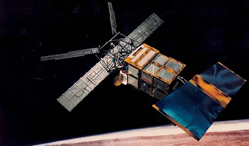
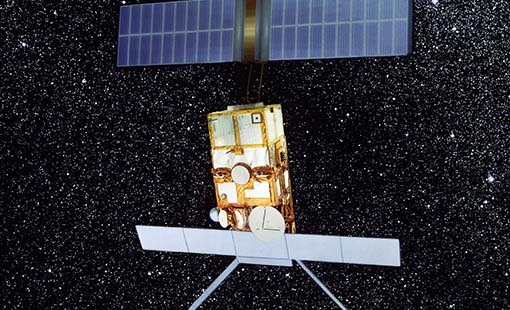
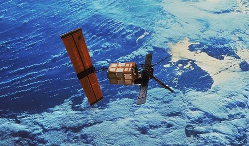
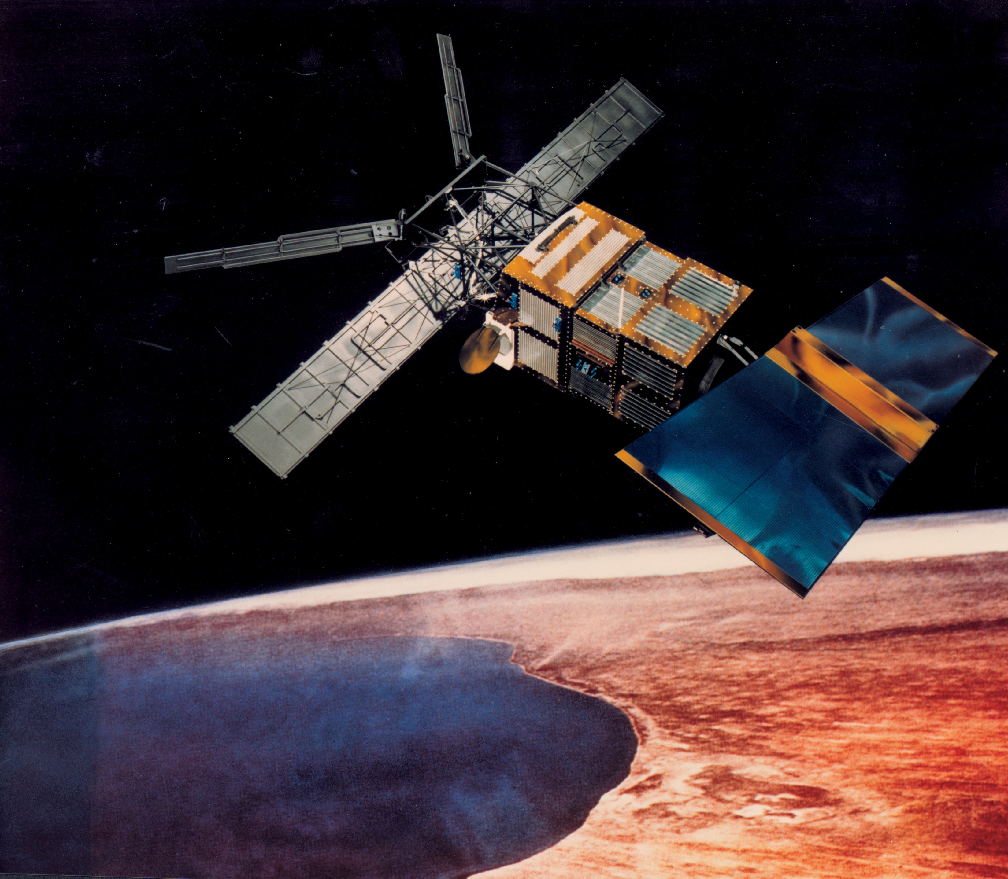
ERS-1/2 Radar Altimeter REAPER Geophysical Data Record - GDR [ERS_ALT_2]
This is a RA Geophysical Data Record (GDR) product containing radar range, orbital altitude, wind speed, wave height and water vapour from the ATSR/MWR as well as geophysical corrections. The REAPER (REprocessing of Altimeter Products for ERS) product is generated by applying a similar processing as for Envisat RA-2 on the Level 1b consolidated waveforms using 4 different re-trackers, RA calibration improvement, new precise orbit solution (POD), new ionospheric corrections (NICO09 until 1998 and GIM up to 2003), ECMWF ERA-interim model and updated SSB tables. This product contains two data rates: a low rate of 1 Hz and a high rate of 20 Hz. Most 1 Hz data is also represented at 20 Hz, while microwave radiometer (ATSR/MWR) data and the atmospheric and geophysical corrections are only given at 1 Hz. The REAPER GDR (ERS_ALT_2_) is a global product including data over ocean, ice and land. It should be noted that this product differs from the Envisat RA2 in the following ways: The product format; which is NetCDF (more details can be found in the Product Handbook, and not PDS The product is delivered based on orbit acquisition and not per pass (pole-to-pole). This product is extended through Envisat RA-2 data.
Data - Fast Registration with immediate access (Open)
ERS-1/2 Radar Altimeter REAPER Sensor Geophysical Data Record - SGDR [ERS_ALT_2S]
This is a RA Geophysical Data Record (GDR) product containing radar range, orbital altitude, wind speed, wave height and water vapour from the ATSR/MWR as well as geophysical corrections. The REAPER (REprocessing of Altimeter Products for ERS) product is generated by applying a similar processing as for Envisat RA-2 on the Level 1b consolidated waveforms using 4 different re-trackers, RA calibration improvement, new precise orbit solution (POD), new ionospheric corrections (NICO09 until 1998 and GIM up to 2003), ECMWF ERA-interim model and updated SSB tables. This product contains two data rates: a low rate of 1 Hz and a high rate of 20 Hz. Most 1 Hz data is also represented at 20 Hz, while microwave radiometer (ATSR/MWR) data and the atmospheric and geophysical corrections are only given at 1 Hz. The REAPER GDR (ERS_ALT_2_) is a global product including data over ocean, ice and land. It should be noted that this product differs from the Envisat RA2 in the following ways: The product format; which is NetCDF (more details can be found in the Product Handbook, and not PDS The product is delivered based on orbit acquisition and not per pass (pole-to-pole). This product is extended through Envisat RA-2 data.
Data - Fast Registration with immediate access (Open)
ERS-1/2 Radar Altimeter REAPER METEO Product - [ERS_ALT_2M]
This is a RA Meteo product containing only the 1 Hz parameters for altimeter (surface range, satellite altitude, wind speed and significant wave height at nadir) and ATSR/MWR data (brightness temperature at 23.8 GHz and 36.5 GHz, water vapour content, liquid water content) used to correct altimeter measurements. It also contains the full geophysical corrections. This product corresponds to a subset of the REAPER GDR product (ERS_ALT_2_). The REAPER (REprocessing of Altimeter Products for ERS) product is generated by applying a similar processing as for Envisat RA-2 on the Level 1b consolidated waveforms using 4 different re-trackers, RA calibration improvement, new precise orbit solution (POD), new ionospheric corrections (NICO09 until 1998 and GIM up to 2003), ECMWF ERA-interim model and updated SSB tables. This product contains only the low rate of 1 Hz data. The REAPER Meteo (ERS_ALT_2M) is a global product including data over ocean, ice and land. It should be noted that this product differs from the Envisat RA2 in the following ways: The product format; which is NetCDF (more details can be found in the Product Handbook), and not PDS The product is delivered based on orbit acquisition and not per pass (pole-to-pole). This product is extended through Envisat RA-2 data.
Data - Fast Registration with immediate access (Open)
ERS PRARE Precise Orbit Product (ERS.ORB.POD/ERS.ORB/PRC)
The precise orbit results from a data reduction process in which all available tracking data (Single-Lens Reflex, radar altimeter crossovers, PRARE range and Doppler data) and most accurate correction, transformation and dynamical models are taken into account and in which high level numerical procedures are applied. These orbits are "optimal" achievable representations of the real orbital motion under the circumstances of tracking situation and the "state of the art" model situation. The precise orbit product for the ERS satellites are the satellite ephemeris (position and velocity vector) including time tag, given in a well-defined reference frame, together with the nominal satellite attitude information and a radial orbit correction. Several orbit solutions are currently distributed: A new set of ORB POD (Precise Orbit Determination - REAPER v2) computed with the most updated model standards for the complete ERS-1 and ERS-2 mission. A previous set of ORB POD (REAPER v1) data already available on the ESA dissemination site since 2014, covering the ERS-1 full mission and the ERS-2 mission up to July 2003. ORB PRC which is the original Precise Orbit dataset computed during the ERS mission operations for ERS-1 and ERS-2. In the new POD dataset (REAPER v2) for the ERS-1 and ERS-2 missions, two different orbit solutions are provided together with the combined solution to be used for processing of the radar altimeter measurements and the determination of geodetic/geophysical products: those computed by DEOS (Delft Institute of Earth Observation and Space Systems), and those generated by ESOC (European Space Operations Centre) using different software (GEODYN and NAPEOS respectively). Careful evaluation of the various solutions of REAPER v2 has shown that the DEOS solution for both ERS-1 and ERS-2 has the best performance and is recommended to be used as reference. See the ERS Orbit Validation Report. For the previous version of the POD data set (REAPER v1), with ERS-2 mission data only up to 2003, three different orbit solutions together with the combined solution are available. These precise orbits for ERS-1 and ERS-2 have been computed at DEOS, ESOC, and GFZ (Deutschen GeoForschungsZentrums) using different software and different altimeter databases. Combined solutions have been created using three individual solutions for each satellite. All orbits were derived using consistent models in the same LPOD2005 terrestrial reference frame. These new orbit solutions show notable improvement with respect to DGME04 orbits (Scharroo and Visser, 1998). Thus, RMS crossover differences of new orbits improved by 4-9 mm. Careful evaluation of the various solutions has shown that the combined solution for both ERS-1 and ERS-2 has the best performance. All POD orbit files (REAPER v1/v2) are available in SP3c format.
Data - Fast Registration with immediate access (Open)
ERS-2 GOME Total Column Amount of Trace Gases Product
GOME Level 2 products were generated by DLR on behalf of the European Space Agency, and are the end result of the Level 1 to 2 reprocessing campaign of GOME Level 1 version 4 data with Level 2 GOME Data Processor (GDP) version 5.0 (HDF-5 format). The GOME Level 2 data product comprises the product header, total column densities of ozone and nitrogen dioxide and their associated errors, cloud properties and selected geo-location information, diagnostics from the Level 1 to 2 algorithms and a small amount of statistical information.
Data - Fast Registration with immediate access (Open)
ERS-1/2 SCATTEROMETER Ocean Wind field and Sea Ice probability [ASPS20.H/ASPS20.N]
The ASPS Level 2 products contain, for each node: the radar backscattering sigma nought for the three beams of the instrument, the four aliased wind solutions (Rank 1-4 wind vector) and the de-aliased wind vector flag, the sea-ice probability and sea-ice flag, the YAW quality flag. The wind retrieval is performed with the CMOD5N geophysical model function derived by ECMWF to compute the neutral winds rather than 10 m winds. ASPS L2.0 High resolution products are provided with a spatial resolution of 25x25 km and a grid spacing of 12.5 km. ASPS L2.0 Nominal resolution products are provided with a spatial resolution of 50x50 km and a grid spacing of 25 km. One product covers one orbit from ascending node crossing. Please consult the Product Quality Readme file before using the ERS ASPS data.
Data - Fast Registration with immediate access (Open)
ERS-2 SCATTEROMETER Surface Soil Moisture Time Series and Orbit product in High and Nominal Resolution [SSM.H/N.TS - SSM.H/N]
Surface soil moisture records are derived from the backscatter coefficient measured by the Scatterometer on-board the European Remote Sensing satellite (ERS-2) using the Technische Universität (TU) Wien soil moisture retrieval algorithm called WARP (WAter Retrieval Package). In the WARP algorithm, the relative surface soil moisture estimates, given in degree of saturation Sd, range between 0% and 100% are derived by scaling the normalized backscatter between the lowest/highest backscatter values corresponding to the driest/wettest soil conditions. Surface Soil Moisture - Time Series product: The products generated are the surface soil moisture time series, where for each grid point defined in a DGG (Discrete Global Grid) is stored the time series of soil moisture and its noise, the surface state flag, the geolocation and the satellite parameters. The spatial resolution of the products is about 25 km x 25 km (high resolution) or 50 km x 50 km (nominal resolution) geo-referenced on the WARP grid. The location of the points can be viewed interactively with the tool DGG Point Locator. Surface Soil Moisture - Orbit product: In addition to WARP, a second software package, referred to as WARP orbit, was developed in response to the strong demand of soil moisture estimates in satellite orbit geometry. The Level 2 soil moisture orbit product contains a series of Level 1 data information, such as the backscatter, the incidence angle and the azimuth angle for each triplet together with the surface soil moisture and its noise, normalized backscatter at 40° incidence angle, parameters useful for soil moisture, the geolocation and the satellite parameters. The soil moisture orbit product is available in two spatial resolutions with different spatial sampling distances: Spatial sampling on a regular 12.5 km grid in orbit geometry with a spatial resolution of about 25 km x 25 km (High resolution) Spatial sampling on a regular 25 km grid in orbit geometry with a spatial resolution of about 50 km x 50 km (Nominal resolution). The spatial resolution is defined by the Hamming window function, which is used for re-sample of raw backscatter measurements to the orbit grid in the Level-1 ground processor. Please consult the Product Quality Readme file before using the ERS-2 Surface Soil Moisture data.
Data - Fast Registration with immediate access (Open)
GOME Total Column Water Vapour Climate product
The GOME Total Column Water Vapour (TCWV) Climate product was generated by the Max Planck Institute for Chemistry (MPIC), and the German Aerospace Center (DLR) within the ESA GOME-Evolution project. It is a Level 3 type product containing homogenized time-series of the global distribution of TCWV spanning over more than two decades (1995-2015). The data is provided as single netCDF file, containing monthly mean TCWV (units kg/m2) with 1-degree resolution, and is based on measurements from the satellite instruments ERS-2 GOME, Envisat SCIAMACHY, and MetOp-A GOME-2. Details are available in the paper by Beirle et al, 2018. Please also consult the GOME TCWV Product Quality Readme file before using the data.
Data - EO Sign In Authentication (Open)
ERS-1/2 SAR IM Precision L1 [SAR_IMP_1P]
The SAR Precision product is a multi-look (speckle-reduced), ground range image acquired in Image Mode. This product type is most applicable to users interested in remote sensing applications, but is also suitable for calibration purposes. The products are calibrated and corrected for the SAR antenna pattern and range-spreading loss. Radar backscatter can be derived from the products for geophysical modelling, but no correction is applied for terrain-induced radiometric effects. The images are not geocoded, and terrain distortion (foreshortening and layover) has not been removed. The numbering sequence relates to the satellite position and therefore differs between Ascending and Descending scenes. Product characteristics: Pixel size: 12.5 m (range - across track) x 12.5 m (azimuth - along track) Scene area: 100 km (range) x at least 102.5 km (azimuth) Scene size: 8000 pixels range x at least 8200 lines (azimuth) Pixel depth: 16 bits unsigned integer Total product volume: 125 MB Projection: Ground-range Number of looks: 3.