CHRIS Overview
Instrument Description
CHRIS was an AO hyperspectral instrument whose objective was the collection of BRDF (Bidirectional Reflectance Distribution Function) data for a better understanding of spectral reflectances. CHRIS was the prime instrument of the PROBA-1 mission. The technology objective was to explore the capabilities of imaging spectrometers on agile small satellite platforms. CHRIS provided 19 spectral bands (fully programmable) in the VNIR range (400 - 1050 nm) at a GSD (Ground Sampling Distance) of 17 m. Each nominal image forms a square of 13 km x 13 km on the ground (at perigee).
The observation of the square target area consists of 5 consecutive pushbroom scans by the single-line array detectors, each scan was executed at different view angles to the target within a 55º cone centered at the target zenith. The pushbroom velocity at the target had to reduced by a factor of 5 compared to nominal nadir-pointing velocity in order to increase optimal exposure time. CHRIS could be reconfigured to provide 63 spectral bands at a spatial resolution of about 34 m. The spectral band sets were 19 band read out at 17 m GSD. The CHRIS design was capable of providing up to 150 channels over the spectral range of 400-1050 nm.
| Accuracy | 150 arcsec |
| Spatial Resolution | 18 or 36m |
| Swath Width | 14 km, 18 |
| Waveband | 415-1050 nm |
Design
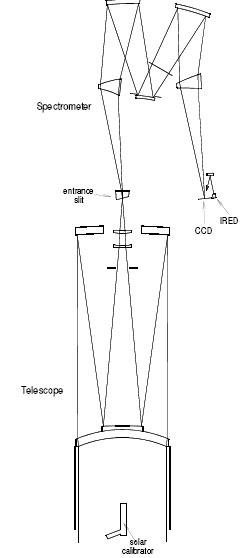
The Compact High Resolution Imaging Spectrometer (CHRIS) was an imaging spectrometer of basically conventional form, with a telescope forming an image of Earth onto the entrance slit of a spectrometer, and an area-array detector at the spectrometer focal plane. The instrument operated in a push-broom mode during Earth imaging. The platform provided pointing in both acrosstrack and along-track directions, for target acquisition and for Bidirectional reflectance distribution function (BRDF) measurements.
The CHRIS instrument design comprised a catadioptric telescope, an imaging spectrometer, and an area detector array at the focal plane of the spectrometer. The technology objective was to explore the capabilities of imaging spectrometers on agile small satellite platforms.
The platform/instrument could be commanded to perform the following functions:
- Target location - requiring roll manoeuvres to point cross-track
- Viewing directions for each target in one orbit - requiring pitch manoeuvres to point along-track
- Spectral bands and spectral sampling interval in each band
- Programmed line integration and dumping on chip for spectral band selection
- Pixel integration on chip for spatial resolution control
- Correlated double sampling (noise reduction circuit)
- Dynamic gain switch for optimum usage of the ADC resolution
- Spatial sampling interval.
The atmospheric science objectives of CHRIS focused on aerosols, which as well as being important for weather and climate, are also a consideration for accurate atmospheric correction of satellite data. Operational plans called for a total of 30 test sites: 15 for aerosol/atmosphere studies, 10 for land surface studies and five for coastal studies. Aerosol studies included a number of different continental, marine, urban and desert test sites. Land surface sites included temperate agricultural areas, boreal forests and semi-arid areas.
The combination of the PROBA platform and the CHRIS instrument provided unique potential for Earth imaging. It allowed hyperspectral image data to be obtained at up to five different sensor view angles during a single orbital overpass through along-track pointing and, cloud-cover permitting, up to 15 looks at the same target within a period of a few days from multiple orbital overpasses. These data could be used to derive information on the biophysical and biochemical properties of the land surface, atmosphere and coastal and inland waters through, for example, the numerical or analytical inversion of BRDF models.
The platform also provided slow pitch during imaging in order to increase the integration time of the instrument. This increase in integration time is needed to achieve the target radiometric resolution, at the baseline spatial and spectral sampling interval, and also allows relatively large numbers of bands to be recorded. The pitch rate was varied, as a function of the view direction, to achieve a consistent 17 m alongtrack sampling distance associated with the nominal integration period. The integration time was increased, compared with that which would be achieved without pitch adjustment, by a factor 5.
The spectral waveband covered by the instrument was limited to 1050 nm in the near-IR by the upper limit for useful response of silicon detectors, and to 415 nm in short visible wavelengths by limitations of coating performance.
Telescope
The telescope design form was selected mainly for lowcost and easy assembly within a tight schedule for development. It was an axially-symmetrical two-mirror system, with a concave primary mirror and a convex secondary. Lens elements were used to allow all surfaces to be spherical, and to provide acceptable correction for a moderate field. The front element was a meniscus lens that essentially provided correction for spherical aberration; it also provided a convenient location for the secondary mirror, which was cemented to it.
Two small lens elements near the focal plane extended correction for off-axis aberrations, and corrected chromatic aberration of the meniscus.
| Focal Length | 746 mm |
|---|---|
| Length - lens 1 to slit | 325 mm |
| Baffle Length | 150 mm |
| Entrance Pupil | Tt front lens |
| Exit Pupil | Telecentric |
| Aperture Diameter | 120 mm |
| Aperture Obscuration | 58 mm x 66 mm |
| Field Angle | 1.3 degrees |
| Lens Material | Fused quartz |
All optical components were made of fused quartz, except for the primary mirror; the primary was in a common optical glass to provide an approximate CTE match with titanium structure, in order to control variations in focus with temperature. The lenses were broad-band anti-reflection coated for the range 415 nm to 1050 nm. The mirror coatings were multiple dielectric layers, providing >98% reflectance over this range.
The axially symmetrical design allowed easy manufacture, but had some significant disadvantages. A large axial obstruction of the aperture (by the secondary mirror) reduced the efficiency of the system as a function of optics diameters. There were detailed problems in control of stray light that could reach the entrance slit without reflection at either mirror.
Most significantly, efficient anti-reflection coatings were needed to control stray light due to double reflections within the telescope system. Good anti-reflection coatings were not feasible for much wider spectral ranges, so that the design would be considered inappropriate for systems covering the short-wave IR spectral band (SWIR, typically out to 2400 nm), in addition to the visible/near-IR (VNIR) band current covered by CHRIS.
CHRIS Spectrometer
| Magnification | Unity |
|---|---|
| Spectral spread over 22.5 microns at detector | 1.25 nm at 400 nm 11 nm at 1050 nm |
| Length, slit to rear mirror | 265 mm |
| Width, slit to detector | 125 mm |
Spectral dispersion was provided by refracting prisms that were integrated into a mirror relay system. The relay comprised three mirrors, two large concave mirrors and one smaller convex mirror, similar to a conventional Offner configuration that gives unit magnification. The Offner did not provide a collimated light path, in which flat prism surfaces would introduce no image-blurring aberrations. It was desirable for the prism surfaces to be curved in order to provide good spatial and spectral resolution at the focal plane.
The curvatures essentially provided control over spherical aberration; other aberrations were controlled by the balance between angles of incidence on surfaces of the prisms and mirrors. A minimum of two prisms – one in a diverging beam and one in a converging beam – was needed to control a higher-order astigmatism term (at 45. to the principle plane and varying linearly with field angle) that was introduced by axial asymmetry. The design only had spherical surfaces. It used fused quartz for the prisms; the spectrometer mirrors were made in a common optical glass, as for the telescope primary.
The design using curved prisms was capable of correction for the distortions of the final image that were usually called "smile" and "frown". Smile is curvature and tilt of the image of a straight entrance slit, which introduces a nonuniformity in the wavelengths defined by each row of detector elements. Frown is a variation in tilt of the spectra associated with each point on ground, introducing errors in spatial registration of spectral data read from parallel detector columns.
The spectrometer provided registration to better than 5% of the pixel in both spectral and spatial directions, with resolution limited essentially by the detector pixel size.
Baffling
In the axially symmetrical telescope design, stray light could arrive at the entrance slit without reflection at either of the two telescope mirrors. In the section orthogonal to the slit, this stray path was blocked effectively by a slot baffle in front of the small lens assembly. This did not prevent stray light from reaching the slit from areas of the aperture on either side of the secondary mirror, in the section parallel with the slit. However, this stray light was blocked inside the spectrometer by masks located between the secondary and tertiary mirrors, where the optics formed an image of the secondary mirror.
The external baffle did not have a very significant role in control of stray light, marginally reducing scatter from telescope optics by reducing their illumination of from the scene. The external baffle was needed mainly to limit temperature variations in spectrometer optics due to variations in radiant inputs from the scene; for this purpose, the baffle was metallic, and conductively coupled to the telescope structure.
Structure and thermal design
The telescope and spectrometer were constructed mainly in titanium – this choice dictated mainlyby considerations of cost and manufacturing schedule. An optical bench approach was used for the spectrometer, while conventional cylindrical structures were used for the axially-symmetrical telescope. Telescope and spectrometer were mounted on a common titanium bulkhead. Aluminium was used for baffles, the spectrometer cover and a radiation shield for the detector. The detector was mounted on a 1 kgm block of aluminium to provide thermal inertia.
The system was conductively isolated from the platform by use of three low-conductivity feet that also provided flexure to isolate the instrument from stresses induced by differential expansion with respect to the (aluminium) mounting plate. Radiant isolation was provided by MLI wrapping of the instrument.
Orbital temperature variations were driven mainly by variation in radiant input from Earth in the solar spectral band. This produced a few degrees temperature variation in the telescope front optics – not enough to have a significant effect on telescope resolution. The spectrometer was effectively isolated from this front-end variation by the low conductivity of the titanium structure.
Detectors and Electronics

The CCD detector was an area array from e2v (CCD25-20) with 1152 rows and 780 columns, and a 22.5 x 22.5 μm pixel size. The device was thinned and back-illuminated to provide good blue response. It operated in a frame transfer mode, with 576 rows in the image and masked storage zones. The opaque mask was extended along the sides of the image zone to provide 16 transition and dark reference pixels at each end of each CCD row, which were used for dark signal and electronic offset calibration. The spectrometer image filled <200 of the CCD rows, but part of the nominally-unexposed area was used to provide data to compensate for stray light and CCD smear effects. The CCD incorporated a dump gate adjacent to the readout shift register. This provided a facility for fast parallel dumping of charge for regions of the CHRIS spectrum that were not selected for readout.
The instrument electronics include:
- Programmed line integration and dumping on chip for spectral band selection
- Pixel integration on chip for spatial resolution control
- Correlated double sampling (noise reduction circuit)
- Dynamic gain switch for optimum usage of the ADC resolution
- 12 bit ADC.
There was considerable useful flexibility in operation of the CCD. It offered the facility to sum sets of row-signals in the shift register, before read-out – providing users with a facility to compose spectral bands of optimum widths. Signals could also be binned in pairs at the output port, relaxing across-track spatial resolution by a factor 2, and integration time could be increased over a wide range to provide control of spatial resolution along-track (in combination with control over the platform pitch rate). The system also allowed images to be restricted to half swath widths to increase the number of spectral bands that can be read out. It was possible to read out 18 spectral bands during a nominal integration time of 12.7 ms, plus one band assigned to smear/stray light calibration in each frame.
This spectral coverage was associated with optimum spatial resolution and maximum swath width. However, it was possible to read out much larger numbers of spectral bands with relaxation of spatial resolution and/or swath width. Relaxed ground sampling distance (associated with increased integration periods) provided enhanced signal-to-noise ratios.
Relaxed ground sampling distance (associated with increased integration periods) provided enhanced signal-to-noise ratios.
Offsetting dark signal and smear, the CHRIS detectors provided masked and overscan pixels in each row, that were used to provide data on electronic offsets and average dark signal levels. Full-frame dark calibration was achieved by a combination of data from full dark-field frames, read while the platform was over dark Earth areas, with masked pixel data.
The masked pixel data were used to correct the full dark fields for effects of temperature drifts between dark-scene and light-scene measurements. The CCD generated an error due to collection of signal during frame transfer. The error was a weighted average of the signal collected over the whole image area in each column, and was measured using detector rows outside the image area, which received only the smear signal during frame transfer.
Response and wavelength calibration

Vicarious methods had been used to provide response calibration for CHRIS. Flat-fielding (relative response between pixels across the field, in each spectrally resolved band) had relied on analysis of data from real scenes, with preference for bland scenes, to detect pixel-topixel response variations. In-flight wavelength calibration relied on location of the oxygen absorption band at 762 nm, using image data from suitable scenes. This again avoided the need for potentially expensive addition flight hardware.
The atmosphere absorption data was used to update full pre-flight data, including smile errors. The instrument also included a "solar calibration device", which was attached to the instrument at the front end of the external baffle. It was a very simple system, comprising essentially a plano-convex lens in fused quartz, integrated with a prism that reflects sunlight into the lens.
The lens had a focal length of 25 mm, and formed an image of the sun approximately 0.2mm diameter outside the telescope pupil. The light from the sun image spreaded over the small field of the instrument to fill the spectrometer entrance slit and the detector image area.
The focal length of the lens was selected, as a fraction of the aperture diameter, to provide an effective radiance (actual sun-image radiance averaged over the instrument aperture area) equivalent to that of a diffuser in sunlight with 25% reflectance. It therefore provided signals in the instrument dynamic range. The device had been calibrated on ground for effective reflectance, using a sun-simulator and a standard diffuser, so that it could be used like a full-aperture diffuser in flight.
The solar calibration device occupied a fixed position in the instrument aperture, and used a small fraction of the aperture for response calibration. This slightly reduced the aperture area available for useful Earth imaging.
During normal Earth imaging, the solar calibration device projected very little light into the main instrument aperture. It was used for calibration when the instrument was over the Antarctic, on the dark side of the terminator – the instrument was in direct sunlight but receiving very little light from ground.
The platform must be yawed to receive sunlight on the lens axis. The field of the device for receiving sunlight was limited to 2. x 4. by a rectangular aperture in the sun-image plane. This field was fully sampled, in pre-flight calibration and in orbit, to check for non-uniformities in transmission of the device and instrument optics over a small area and thus to detect signs of local optics contamination that would obstruct the narrow calibration beam and invalidate the calibration.
The key advantage of the solar calibration device, for the CHRIS development, is that it was very cheap and simple compared with a system using one or more full-aperture diffusers. Because the device used a small, dedicated aperture area, it requires no moving parts. A clear disadvantage is that it sampled only a very small part of the main instrument aperture, so that changes in optics transmission that are not uniform across the aperture would not be accurately measured.
An internal LED source was included in the instrument, close to the detector. Light from the LED was reflected onto the detector by a diffuser mounted above the detector, but out of the main light path.
The initial purpose of the LED was only to check function of the detection system during integration, but the LED had also been used to check linearity in flight.
Payload temperature was measured during each image acquisition. Changes in radiometric and wavelength calibration were investigated as a function of the indicated spectrometer temperatures.
Pre-flight calibration supported important pre-flight calibration exercises for CHRIS include:
- Absolute radiometric response and calibration of the solar calibration device in operation with a sun-simulator
- Full wavelength calibration against detector row numbers.
Other normal measurements made on ground included: spectral and spatial resolution, spectral and spatial registration, temperature variations of wavelengths and registration, stray light, linearity, and detection system noise.
CHRIS Resources
- The Compact High Resolution Imaging Spectrometer (CHRIS): the Future of Hyperspectral Satellite Sensors. Imagery of Oostende Coastal and Inland Waters.
- CHRIS Data Format
- Note on CHRIS Acquisition Procedure and Image Geometry
- First Results from the PROBA/CHRIS Hyperspectral/Multiangular Satellite System Over Land and Water Targets