- All Categories (36)
- Data (5)
- News (11)
- Missions (2)
- Events (10)
- Activities (1)
- Campaigns (1)
- Documents (6)
News - General News
Go-to guide to Third Party Mission data offering
ESA’s latest Third Party Missions Data Access Guide has been published, providing technical details and information on available data collections for all current or past Third Party Missions.
News - Thematic area articles
How to use space data to probe humankind’s ancient past
Data disseminated by ESA’s Third Party Missions (TPM) programme are enabling archaeological investigations that could help to unravel the mysteries of past societies and cultures.
News - Infographics
Discover how RADARSAT scans Earth's surface
Learn about how RADARSAT scans Earth's surface in our new infographic.
News - Thematic area articles
Monitoring water on Earth's surface
ESA's Earth observation satellites are playing a leading role in furthering our understanding of how Earth's terrestrial hydrosphere is being influenced by humankind.
News - Data Release news

Two new ESA archive collections have been opened for PlanetScope and SkySat
PlanetScope ESA archive and SkySat ESA archive collections are available through ESA’s Third Party Missions programme via Fast Approval Registration.
Data - Fast Registration with approval (Restrained)
SkySat ESA archive
The SkySat ESA archive collection consists of SkySat products requested by ESA supported projects over their areas of interest around the world and that ESA collected over the years. The dataset regularly grows as ESA collects new products. Two different product types are offered, Ground Sampling Distance at nadir up to 65 cm for panchromatic and up to 0.8m for multi-spectral. EO-SIP Product Type Product Description Content SSC_DEF_SC Basic and Ortho scene Level 1B 4-bands Analytic /DN Basic scene Level 1B 4-bands Panchromatic /DN Basic scene Level 1A 1-band Panchromatic DN Pre Sup resolution Basic scene Level 3B 3-bands Visual Ortho Scene Level 3B 4-bands Pansharpened Multispectral Ortho Scene Level 3B 4-bands Analytic/DN/SR Ortho Scene Level 3B 1-band Panchromatic /DN Ortho Scene SSC_DEF_CO Ortho Collect Visual 3-band Pansharpened Image Multispectral 4-band Pansharpened Image Multispectral 4-band Analytic/DN/SR Image (B, G, R, N) 1-band Panchromatic Image The Basic Scene product is uncalibrated, not radiometrically corrected for atmosphere or for any geometric distortions inherent in the imaging process: Analytic - unorthorectified, radiometrically corrected, multispectral BGRN Analytic DN - unorthorectified, multispectral BGRN Panchromatic - unorthorectified, radiometrically corrected, panchromatic (PAN) Panchromatic DN - unorthorectified, panchromatic (PAN) L1A Panchromatic DN - unorthorectified, pre-super resolution, panchromatic (PAN) The Ortho Scene product is sensor and geometrically corrected, and is projected to a cartographic map projection: Visual - orthorectified, pansharpened, and colour-corrected (using a colour curve) 3-band RGB Imagery Pansharpened Multispectral - orthorectified, pansharpened 4-band BGRN Imagery Analytic SR - orthorectified, multispectral BGRN. Atmospherically corrected Surface Reflectance product. Analytic - orthorectified, multispectral BGRN. Radiometric corrections applied to correct for any sensor artifacts and transformation to top-of-atmosphere radiance. Analytic DN - orthorectified, multispectral BGRN, uncalibrated digital number imagery product Radiometric corrections applied to correct for any sensor artifacts Panchromatic - orthorectified, radiometrically correct, panchromatic (PAN) Panchromatic DN - orthorectified, panchromatic (PAN), uncalibrated digital number imagery product The Ortho Collect product is created by composing SkySat Ortho Scenes along an imaging strip. The product may contain artifacts resulting from the composing process, particular offsets in areas of stitched source scenes. Spatial coverage: Check the spatial coverage of the collection on a map available on the Third Party Missions Dissemination Service. As per ESA policy, very high-resolution imagery of conflict areas cannot be provided.
News - Data Release news

PlanetScope and Skysat data available through ESA’s Third Party Missions Programme
Through ESA’s Third Party Missions Programme, researchers, scientists and companies from around the world can apply to access Planet’s high-frequency, high-resolution satellite data for non-commercial use.
News - Success Stories
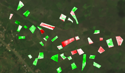
Predicting crop yield using Planet data
The world’s population continues to grow, while the climate crisis is raising Earth’s temperatures and increasing the likelihood of extreme weather events – all of which affect food security.
News - Infographics
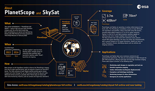
PlanetScope and SkySat - The high-resolution nanosatellite constellation
Find out more about the PlanetScope and SkySat missions in our new infographic.
Event - Workshop

Coastal and Marine Applications of SAR Workshop 2003
The second in the Coastal and Marine Applications of SAR Workshop series covered a range of topics on applications of synthetic aperture radar (SAR) in coastal and marine environments.
News - Infographics
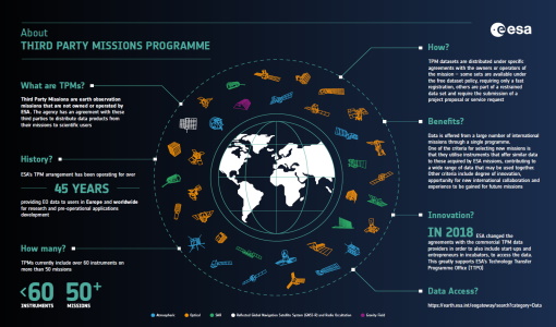
An overview of ESA's Third Party Missions programme
ESA’s Third Party Missions programme consists of almost 50 satellite missions, which are owned by organisations around the world. ESA has agreements with these organisations to acquire, process, and distribute data from their missions
News - Data Release news
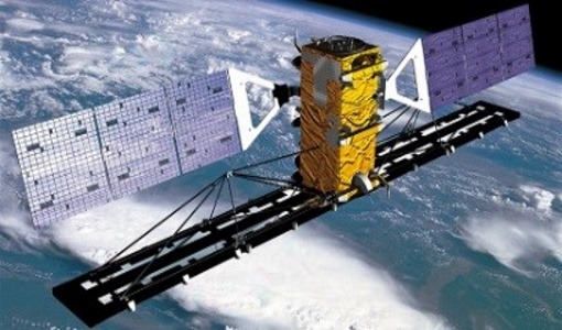
RADARSAT-2 ESA archive online collection
The RADARSAT-2 ESA archive collection is now available on TPM LOADS Dissemination server.
Data - Fast Registration with approval (Restrained)
RADARSAT-2 ESA archive
The RADARSAT-2 ESA archive collection consists of RADARSAT-2 products requested by ESA supported projects over their areas of interest around the world. The dataset regularly grows as ESA collects new products over the years. Following Beam modes are available: Standard, Wide Swath, Fine Resolution, Extended Low Incidence, Extended High Incidence, ScanSAR Narrow and ScanSAR Wide. Standard Beam Mode allows imaging over a wide range of incidence angles with a set of image quality characteristics which provides a balance between fine resolution and wide coverage, and between spatial and radiometric resolutions. Standard Beam Mode operates with any one of eight beams, referred to as S1 to S8, in single and dual polarisation . The nominal incidence angle range covered by the full set of beams is 20 degrees (at the inner edge of S1) to 52 degrees (at the outer edge of S8). Each individual beam covers a nominal ground swath of 100 km within the total standard beam accessibility swath of more than 500 km. Beam Mode Product Nominal Resolution (metres) Nominal Pixel Spacing Range x Azimuth (metres) Resolution Range x Azimuth (metres) Nominal Scene Size Range x Azimuth (kilometres) Range of Angle of Incidence (degrees) Number of Looks Range x Azimuth Polarisations Options Standard SLC 25 8.0 or 11.8 x 5.1 9.0 or 13.5 x 7.7 100 x 100 20 - 52 1 x 1 Single Pol HH or VV or HV or VH - or - Dual HH + HV or VV + VH SGX 8.0 x 8.0 26.8 - 17.3 x 24.7 1 x 4 SGF 12.5 x 12.5 SSG, SPG Wide Swath Beam Mode allows imaging of wider swaths than Standard Beam Mode, but at the expense of slightly coarser spatial resolution. The three Wide Swath beams, W1, W2 and W3, provide coverage of swaths of approximately 170 km, 150 km and 130 km in width respectively, and collectively span a total incidence angle range from 20 degrees to 45 degrees. Polarisation can be single and dual. Beam Mode Product Nominal Resolution (metres) Nominal Pixel Spacing Range x Azimuth (metres) Resolution Range x Azimuth (metres) Nominal Scene Size Range x Azimuth (kilometres) Range of Angle of Incidence (degrees) Number of Looks Range x Azimuth Polarisations Options Wide SLC 30 11.8 x 5.1 13.5 x 7.7 150 x 150 20 - 45 1 x 1 Single: Pol HH or VV or HV or VH - or - Dual: HH + HV or VV + VH SGX 10 x 10 40.0 - 19.2 x 24.7 1 x 4 SGF 12.5 x 12.5 SSG, SPG Fine Resolution Beam Mode is intended for applications which require finer spatial resolution. Products from this beam mode have a nominal ground swath of 50 km. Nine Fine Resolution physical beams, F23 to F21, and F1 to F6 are available to cover the incidence angle range from 30 to 50 degrees. For each of these beams, the swath can optionally be centred with respect to the physical beam or it can be shifted slightly to the near or far range side. Thanks to these additional swath positioning choices, overlaps of more than 50% are provided between adjacent swaths. RADARSAT-2 can operate in single and dual polarisation for this beam mode. Beam Mode Product Nominal resolution (metres) Nominal Pixel Spacing Range x Azimuth (metres) Resolution Range x Azimuth (metres) Nominal Scene Size Range x Azimuth (kilometres) Range of Angle of Incidence (degrees) Number of Looks Range x Azimuth Polarisations Options Fine SLC 8 4.7 x 5.1 5.2 x 7.7 50 x 50 30 - 50 1 x 1 Single: Pol HH or VV or HV or VH - or - Dual: HH + HV or VV + VH SGX 3.13 x 3.13 10.4 - 6.8 x 7.7 1 x 1 SGF 6.25 x 6.25 SSG, SPG In the Extended Low Incidence Beam Mode, a single Extended Low Incidence Beam, EL1, is provided for imaging in the incidence angle range from 10 to 23 degrees with a nominal ground swath coverage of 170 km. Some minor degradation of image quality can be expected due to operation of the antenna beyond its optimum scan angle range. Only single polarisation is available. Beam Mode Product Nominal resolution (metres) Nominal Pixel Spacing Range x Azimuth (metres) Resolution Range x Azimuth (metres) Nominal Scene Size Range x Azimuth (kilometres) Range of Angle of Incidence (degrees) Number of Looks Range x Azimuth Polarisations Options Extended Low SLC 25 8.0 x 5.1 9.0 x 7.7 170 x 170 10 - 23 1 x 1 Single: HH SGX 10.0 x 10.0 52.7 - 23.3 x 24.7 1 x 4 SGF 12.5 x 12.5 SSG, SPG In the Extended High Incidence Beam Mode, six Extended High Incidence Beams, EH1 to EH6, are available for imaging in the 49 to 60 degree incidence angle range. Since these beams operate outside the optimum scan angle range of the SAR antenna, some degradation of image quality, becoming progressively more severe with increasing incidence angle, can be expected when compared with the Standard Beams. Swath widths are restricted to a nominal 80 km for the inner three beams, and 70 km for the outer beams. Only single polarisation available. Beam Mode Product Nominal resolution (metres) Nominal Pixel Spacing Range x Azimuth (metres) Resolution Range x Azimuth (metres) Nominal Scene Size Range x Azimuth (kilometres) Range of Angle of Incidence (degrees) Number of Looks Range x Azimuth Polarisations Options Extended High SLC 25 11.8 x 5.1 13.5 x 7.7 75 x 75 49 - 60 1 x 1 Single Pol HH SGX 8.0 x 8.0 18.2 - 15.9 x 24.7 1 x 4 SGF 12.5 x 12.5 SSG, SPG ScanSAR Narrow Beam Mode provides coverage of a ground swath approximately double the width of the Wide Swath Beam Mode swaths. Two swath positions with different combinations of physical beams can be used: SCNA, which uses physical beams W1 and W2, and SCNB, which uses physical beams W2, S5, and S6. Both options provide coverage of swath widths of about 300 km. The SCNA combination provides coverage over the incidence angle range from 20 to 39 degrees. The SCNB combination provides coverage over the incidence angle range 31 to 47 degrees. RADARSAT-2 can operate in single and dual polarisation for this beam mode. Beam Mode Product Nominal resolution (metres) Nominal Pixel Spacing Range x Azimuth (metres) Resolution Range x Azimuth (metres) Nominal Scene Size Range x Azimuth (kilometres) Range of Angle of Incidence (degrees) Number of Looks Range x Azimuth Polarisations Options ScanSAR Narrow SCN, SCF, SCS 20 25 x 25 81 - 38 x 40 - 70 300 x 300 20 - 46 2 x 2 Single Co or Cross: HH or VV or HV or VH - or - Dual: HH + HV or VV + VH ScanSAR Wide Beam Mode provides coverage of a ground swath approximately triple the width of the Wide Swath Beam Mode swaths. Two swath positions with different combinations of physical beams can be used: SCWA, which uses physical beams W1, W2, W3, and S7, and SCWB, which uses physical beams W1, W2, S5 and S6. The SCWA combination allows imaging of a swath of more than 500 km covering an incidence angle range of 20 to 49 degrees. The SCWB combination allows imaging of a swath of more than 450 km covering the incidence angle. Polarisation can be single and dual. Beam Mode Product Nominal resolution (metres) Nominal Pixel Spacing Range x Azimuth (metres) Resolution Range x Azimuth (metres) Nominal Scene Size Range x Azimuth (kilometres) Range of Angle of Incidence (degrees) Number of Looks Range x Azimuth Polarisations Options ScanSAR Wide SCW, SCF, SCS 100 50 x 50 163 - 73 x 78 - 106 500 x 500 20 - 49 4 x 2 Single Co or Cross: HH or VV or HV or VH - or - Dual: HH + HV or VV + VH These are the different products : SLC (Single Look Complex): Amplitude and phase information is preserved. Data is in slant range. Georeferenced and aligned with the satellite track SGF (Path Image): Data is converted to ground range and may be multi-look processed. Scene is oriented in direction of orbit path. Georeferenced and aligned with the satellite track. SGX (Path Image Plus): Same as SGF except processed with refined pixel spacing as needed to fully encompass the image data bandwidths. Georeferenced and aligned with the satellite track SSG(Map Image): Image is geocorrected to a map projection. SPG (Precision Map Image): Image is geocorrected to a map projection. Ground control points (GCP) are used to improve positional accuracy. SCN(ScanSAR Narrow)/SCF(ScanSAR Wide) : ScanSAR Narrow/Wide beam mode product with original processing options and metadata fields (for backwards compatibility only). Georeferenced and aligned with the satellite track SCF (ScanSAR Fine): ScanSAR product equivalent to SGF with additional processing options and metadata fields. Georeferenced and aligned with the satellite track SCS(ScanSAR Sampled) : Same as SCF except with finer sampling. Georeferenced and aligned with the satellite track. Spatial coverage: Check the spatial coverage of the collection on a map available on the Third Party Missions Dissemination Service.
Document - Conference Presentation - Poster

8_Nicole Dore_pdf.pdf
RADARSAT-2 polarimetric multi incidence angle analysis over Archaeological Site - the UNESCO ancient city of Samarra (Iraq) N. Dore [University of Rennes1 - France]
Document - Conference Presentation - Poster
7_Patruno.pdf
Multi frequency polarimetric SAR sensors analysis - The archaeological UNESCO site of Djebel Barkal (Sudan) J. Patruno [Univerisity of Rennes1 - France]
Document - Conference Presentation - Poster
4_POLinSAR2013_Ban_KTH.pdf
Multitemporal RADARSAT-2 Fine-Beam Polarimetric SAR for Urban Land Cover Mapping Y. Ban [KTH Royal Institute of Technology - Sweden]
News - Data Release news
RADARSAT data on demand
In the framework of the Earthnet programme, ESA is distributing RADARSAT data on-demand to support EO science and research activities.
Event - Training
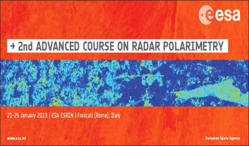
2nd Advanced Course on Radar Polarimetry 2013
The advanced ESA course provided an introduction to the basics and advanced concepts of theory, scattering concepts, systems and applications typical of radar polarimetric remote sensing.
Event - Workshop

POLinSAR 2013
The objectives of the PolInSAR 2013 workshop were to present the latest studies and results of SAR polarimetry and polarimetric interferometry.
Data - Project Proposal (Restrained)
SkySat Full Archive and New Tasking
The SkySat Level 2B Basic Scene, Level 3B Ortho Scene and Level 3B Consolidated full archive and new tasking products are available as part of Planet imagery offer. The SkySat Basic Scene product is uncalibrated and in a raw digital number format, not corrected for any geometric distortions inherent in the imaging process. Rational Polynomial Coefficients (RPCs) is provided to enable orthorectification by the user. Basic Scene Product Components and Format Processing Levels Analytic (unorthorectified, radiometrically corrected, multispectral BGRN) Analytic DN (unorthorectified, multispectral BGRN) Panchromatic DN (unorthorectified, panchromatic) Product Components and Format Image File (GeoTIFF format) Metadata File (JSON format) Rational Polynomial Coefficients (Text File) UDM File (GeoTIFF format) Image Configuration 4-band Analytic DN Image (Blue, Green, Red, NIR) 1-band Panchromatic DN Image (Pan) Ground Sampling Distance 3.7 m at nadir (average at reference altitude 475 km) Ground Sampling Distance (nadir) Panchromatic 0.86m and Multispectral 1.0m for SkySat-1&2 Panchromatic 0.65m and Multispectral 0.8m for SkySat-3 to 13 (0.72 m and 1.0m for data acquired before 30/06/2020) Accuracy <50 m RMSE The SkySat Ortho Scene is sensor- and geometrically-corrected (by using DEMs with a post spacing of between 30 and 90 meters) and is projected to a cartographic map projection; the accuracy of the product will vary from region to region based on available GCPs. Different products are available: The SkySat Visual Ortho Scene product is orthorectified, pansharpened, and color-corrected (using a color curve) 3-band RGB Imagery The SkySat Pansharpened Multispectral Scene product is orthorectified, pansharpened 4-band BGRN Imagery The SkySat Analytic DN Ortho Scene product is orthorectified, multispectral BGRN, uncalibrated, digital number imagery product. The product has been processed to remove distortions caused by terrain; It eliminates the perspective effect on the ground (not on buildings), restoring the geometry of a vertical shot. Transformation to at-sensor radiance is not included The SkySat Panchromatic DN Ortho Scene product is orthorectified, panchromatic, uncalibrated, digital number imagery product. It has a finer GSD than the Analytic Product. Transformation to at-sensor radiance is not included. The SkySat Analytic Ortho Scene are calibrated multispectral imagery products with radiometric corrections applied to correct for any sensor artifacts and transformation to top-of-atmosphere radiance. The SkySat Consolidated Product are Ortho Collect product created by composing ~60 SkySat Ortho Scenes (Visual, Pansharpened Multispectral, Analytic DN, Panchromatic DN) along an imaging strip into segments Ortho Scene Product Components and Format Visual Ortho Pansharpened Multispectral Analytic DN Ortho Panchromatic DN Ortho Analytic Ortho Product Components and Format Image File (GeoTIFF format) Metadata File (JSON format) Rational Polynomial Coefficients (Text File) UDM File (GeoTIFF format) Image File (GeoTIFF) Metadata File (JSON format) Rational Polynomial Coefficients (Text File) UDM File (GeoTIFF format) Image File (GeoTIFF format) Metadata File (JSON format) Rational Polynomial Coefficients (Text File) UDM File (GeoTIFF format) Image File (GeoTIFF format) Metadata File (JSON format) Rational Polynomial Coefficients (Text File) UDM File (GeoTIFF format) Image File (GeoTIFF format) Metadata File (JSON format) Rational Polynomial Coefficients (Text File) UDM File (GeoTIFF format) Image Configuration 3-band Pansharpened Image (PS Red, PS Green, PS Blue) 4-band Pansharpened Image (PS Blue, PS Green, PS Red, PS NIR) 4-band Analytic DN Image (B, G, R, N) 1-band Panchromatic Image 4-band Analytic Image (B, G, R, N) Ground Sampling Distance 50 cm 50 cm 50 cm 50 cm 50 cm Projection UTM WGS84 UTM WGS84 UTM WGS84 UTM WGS84 UTM WGS84 Accuracy <10 m RMSE <10 m RMSE <10 m RMSE <10 m RMSE radiometric accuracy: +/- 5% Relative accuracy at < 10 degrees off-nadir angle As per ESA policy, very high-resolution imagery of conflict areas cannot be provided.