- All Categories (41)
- Data (16)
- News (6)
- Events (13)
- Tools (1)
- Documents (5)
News - Thematic area articles
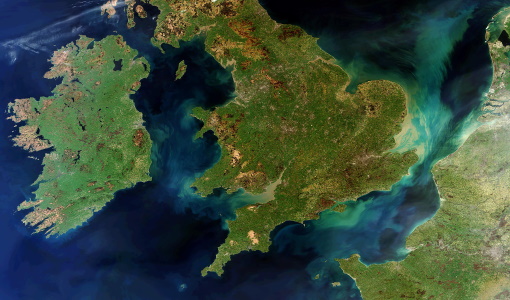
Monitoring water on Earth's surface
ESA's Earth observation satellites are playing a leading role in furthering our understanding of how Earth's terrestrial hydrosphere is being influenced by humankind.
News - Thematic area articles
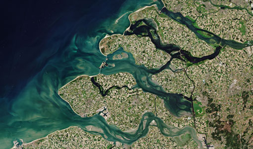
Global understanding of Earth's land surfaces greatly boosted by satellite data
ESA perform land surface monitoring with a range of instruments onboard satellites acquiring optical and radar data. Collections of data from these missions are freely available for research purposes.
Data - EO Sign In Authentication (Open)
PAZ ESA archive
The PAZ ESA archive collection consists of PAZ Level 1 data previously requested by ESA supported projects over their areas of interest around the world and, as a consequence, the products are scattered and dispersed worldwide and in different time windows. The dataset regularly grows as ESA collects new products over the years. Available modes are: StripMap mode (SM): SSD less than 3 m for a scene 30 km x 50 km in single polarization or 15 km x 50 km in dual polarisation ScanSAR mode (SC): the scene is 100 x 150 km2, SSD less than 18 m in signle pol only Wide ScanSAR mode (WS): single polarisation only, with SS less than 40 m and scene size of 270 x 200 km2 Spotlight modes (SL): SSD less than 2 m for a scene 10 km x 10 km, both single and dual polarization are available High Resolution Spotlight mode (HS): in both single and dual polarisation, the scene is 10x5 km2, SSD less than 1 m Staring Spotlight mode (ST): SSD is 25 cm, the scene size is 4 x 4 km2, in single polarisation only. The available geometric projections are: Single Look Slant Range Complex (SSC): single look product, no geocoding, no radiometric artifact included, the pixel spacing is equidistant in azimuth and in ground range Multi Look Ground Range Detected (MGD): detected multi look product, simple polynomial slant-to-ground projection is performed in range, no image rotation to a map coordinate system is performed Geocoded Ellipsoid Corrected (GEC): multi look detected product, projected and re-sampled to the WGS84 reference ellipsoid with no terrain corrections Enhanced Ellipsoid Corrected (EEC): multi look detected product, projected and re-sampled to the WGS84 reference ellipsoid, the image distortions caused by varying terrain height are corrected using a DEM. The following table summarises the offered product types. EO-SIP product type Operation Mode Geometric Projection Geometric Projection PSP_SM_SSC Stripmap (SM) Single Look Slant Range Complex (SSC) PSP_SM_MGD Stripmap (SM) Multi Look Ground Range Detected (MGD) PSP_SM_GEC Stripmap (SM) Geocoded Ellipsoid Corrected (GEC) PSP_SM_EEC Stripmap (SM) Enhanced Ellipsoid Corrected (EEC) PSP_SC_MGD ScanSAR (SC) Multi Look Ground Range Detected (MGD) PSP_SC_GEC ScanSAR (SC) Multi Look Ground Range Detected (MGD) PSP_SC_EEC ScanSAR (SC) Geocoded Ellipsoid Corrected (GEC) PSP_SC_SSC ScanSAR (SC) Enhanced Ellipsoid Corrected (EEC) PSP_SL_SSC Spotlight (SL) Single Look Slant Range Complex (SSC) PSP_SL_MGD Spotlight (SL) Multi Look Ground Range Detected (MGD) PSP_SL_GEC Spotlight (SL) Geocoded Ellipsoid Corrected (GEC) PSP_SL_EEC Spotlight (SL) Enhanced Ellipsoid Corrected (EEC) PSP_HS_SSC High Resolution Spotlight (HS) Single Look Slant Range Complex (SSC) PSP_HS_MGD High Resolution Spotlight (HS) Multi Look Ground Range Detected (MGD) PSP_HS_GEC High Resolution Spotlight (HS) Geocoded Ellipsoid Corrected (GEC) PSP_HS_EEC High Resolution Spotlight (HS) Enhanced Ellipsoid Corrected (EEC) PSP_ST_SSC Staring Spotlight (ST) Single Look Slant Range Complex (SSC) PSP_ST_MGD Staring Spotlight (ST) Multi Look Ground Range Detected (MGD) PSP_ST_GEC Staring Spotlight (ST) Geocoded Ellipsoid Corrected (GEC) PSP_ST_EEC Staring Spotlight (ST) Enhanced Ellipsoid Corrected (EEC) PSP_WS_SSC Wide ScanSAR (WS) Single Look Slant Range Complex (SSC) PSP_WS_MGD Wide ScanSAR (WS) Multi Look Ground Range Detected (MGD) PSP_WS_GEC Wide ScanSAR (WS) Geocoded Ellipsoid Corrected (GEC) PSP_WS_EEC Wide ScanSAR (WS) Enhanced Ellipsoid Corrected (EEC) As per ESA policy, very high-resolution data over conflict areas cannot be provided.
News - Thematic area articles
Satellite data boost global understanding of land surface
Understanding our changing land surface is essential in the study of climate change. Satellites are used to monitor changes to the material that covers Earth’s surface, so-called land cover, such as vegetation and water.
Event - Workshop

Fringe 1996 Workshop
The workshop on ERS SAR Interferometry was open to scientists and students working in the field of Synthetic Aperture Radar (SAR) interferometry and its applications.
Event - Workshop
SEASAR 2008
The "Advances in SAR Oceanography from Envisat and ERS missions" was a thematic workshop on SAR remote sensing techniques for oceanography.
Event - Workshop
Aquaculture User Consultation
The main goal of the workshop was to define a detailed set of user requirements for the future ESA Aquaculture project.
Data - Data Description
Envisat ASAR AP Co- and Cross-polar L0 [ASA_APC/APH/APV_0P]
The ASAR Alternating Polarization Mode Level 0 (Co-polar and Cross-polar H and V) products contain time-ordered Annotated Instrument Source Packets (AISPs) corresponding to one of the three possible polarisation combinations: HH & HV, VV & VH and HH & VV, respectively. The echo samples in the AISPs have been compressed to 4 bits/sample using FBAQ. This is a high-rate, narrow swath mode, so data is only acquired for partial orbit segments. There are two co-registered images per acquisition and may be from one of seven different image swaths. The Level 0 product was produced systematically for all data acquired within this mode. Data Size: 56-100 km across track x 100 km along track. There are three AP Mode Level 0 products: ASA_APH_0P: The Cross-polar H Level 0 product corresponds to the polarisation combination HH/HV. ASA_APV_0P: The Cross-polar V Level 0 product corresponds to the polarisation combination VV/VH. ASA_APC_0P: The Co-polar Level 0 product corresponds to the polarisation combination HH/VV= H and H received/V transmit and V received.
Tools - Other
Hydrology TEP
The Hydrology Thematic Exploitation Platform (TEP) enables access, processing, uploading, visualisation, manipulation and comparison of hydrological data.
News - Success Stories
Using Satellite Data to Predict Floods and Droughts
Scientists are turning to remote sensing to fill the in-situ data gap in hydrological data models in some parts of the world.
News - Success Stories
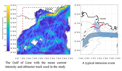
Publication of Coastal Current Intrusions from Satellite Altimetry
A new study entitled “Coastal current intrusions from satellite altimetry” has just been published in the journal Remote Sensing. This study comes from an international collaboration between the European Space Agency (ESA), MIO (Fr), CNR (It) and Serco (It) with the goal of monitoring coastal intrusions into the Gulf of Lion by analyzing multi-mission Satellite Altimetry data with Machine Learning methods
Data - Fast Registration with approval (Restrained)
RADARSAT-2 ESA archive
The RADARSAT-2 ESA archive collection consists of RADARSAT-2 products requested by ESA supported projects over their areas of interest around the world. The dataset regularly grows as ESA collects new products over the years. Following Beam modes are available: Standard, Wide Swath, Fine Resolution, Extended Low Incidence, Extended High Incidence, ScanSAR Narrow and ScanSAR Wide. Standard Beam Mode allows imaging over a wide range of incidence angles with a set of image quality characteristics which provides a balance between fine resolution and wide coverage, and between spatial and radiometric resolutions. Standard Beam Mode operates with any one of eight beams, referred to as S1 to S8, in single and dual polarisation . The nominal incidence angle range covered by the full set of beams is 20 degrees (at the inner edge of S1) to 52 degrees (at the outer edge of S8). Each individual beam covers a nominal ground swath of 100 km within the total standard beam accessibility swath of more than 500 km. Beam Mode Product Nominal Resolution (metres) Nominal Pixel Spacing Range x Azimuth (metres) Resolution Range x Azimuth (metres) Nominal Scene Size Range x Azimuth (kilometres) Range of Angle of Incidence (degrees) Number of Looks Range x Azimuth Polarisations Options Standard SLC 25 8.0 or 11.8 x 5.1 9.0 or 13.5 x 7.7 100 x 100 20 - 52 1 x 1 Single Pol HH or VV or HV or VH - or - Dual HH + HV or VV + VH SGX 8.0 x 8.0 26.8 - 17.3 x 24.7 1 x 4 SGF 12.5 x 12.5 SSG, SPG Wide Swath Beam Mode allows imaging of wider swaths than Standard Beam Mode, but at the expense of slightly coarser spatial resolution. The three Wide Swath beams, W1, W2 and W3, provide coverage of swaths of approximately 170 km, 150 km and 130 km in width respectively, and collectively span a total incidence angle range from 20 degrees to 45 degrees. Polarisation can be single and dual. Beam Mode Product Nominal Resolution (metres) Nominal Pixel Spacing Range x Azimuth (metres) Resolution Range x Azimuth (metres) Nominal Scene Size Range x Azimuth (kilometres) Range of Angle of Incidence (degrees) Number of Looks Range x Azimuth Polarisations Options Wide SLC 30 11.8 x 5.1 13.5 x 7.7 150 x 150 20 - 45 1 x 1 Single: Pol HH or VV or HV or VH - or - Dual: HH + HV or VV + VH SGX 10 x 10 40.0 - 19.2 x 24.7 1 x 4 SGF 12.5 x 12.5 SSG, SPG Fine Resolution Beam Mode is intended for applications which require finer spatial resolution. Products from this beam mode have a nominal ground swath of 50 km. Nine Fine Resolution physical beams, F23 to F21, and F1 to F6 are available to cover the incidence angle range from 30 to 50 degrees. For each of these beams, the swath can optionally be centred with respect to the physical beam or it can be shifted slightly to the near or far range side. Thanks to these additional swath positioning choices, overlaps of more than 50% are provided between adjacent swaths. RADARSAT-2 can operate in single and dual polarisation for this beam mode. Beam Mode Product Nominal resolution (metres) Nominal Pixel Spacing Range x Azimuth (metres) Resolution Range x Azimuth (metres) Nominal Scene Size Range x Azimuth (kilometres) Range of Angle of Incidence (degrees) Number of Looks Range x Azimuth Polarisations Options Fine SLC 8 4.7 x 5.1 5.2 x 7.7 50 x 50 30 - 50 1 x 1 Single: Pol HH or VV or HV or VH - or - Dual: HH + HV or VV + VH SGX 3.13 x 3.13 10.4 - 6.8 x 7.7 1 x 1 SGF 6.25 x 6.25 SSG, SPG In the Extended Low Incidence Beam Mode, a single Extended Low Incidence Beam, EL1, is provided for imaging in the incidence angle range from 10 to 23 degrees with a nominal ground swath coverage of 170 km. Some minor degradation of image quality can be expected due to operation of the antenna beyond its optimum scan angle range. Only single polarisation is available. Beam Mode Product Nominal resolution (metres) Nominal Pixel Spacing Range x Azimuth (metres) Resolution Range x Azimuth (metres) Nominal Scene Size Range x Azimuth (kilometres) Range of Angle of Incidence (degrees) Number of Looks Range x Azimuth Polarisations Options Extended Low SLC 25 8.0 x 5.1 9.0 x 7.7 170 x 170 10 - 23 1 x 1 Single: HH SGX 10.0 x 10.0 52.7 - 23.3 x 24.7 1 x 4 SGF 12.5 x 12.5 SSG, SPG In the Extended High Incidence Beam Mode, six Extended High Incidence Beams, EH1 to EH6, are available for imaging in the 49 to 60 degree incidence angle range. Since these beams operate outside the optimum scan angle range of the SAR antenna, some degradation of image quality, becoming progressively more severe with increasing incidence angle, can be expected when compared with the Standard Beams. Swath widths are restricted to a nominal 80 km for the inner three beams, and 70 km for the outer beams. Only single polarisation available. Beam Mode Product Nominal resolution (metres) Nominal Pixel Spacing Range x Azimuth (metres) Resolution Range x Azimuth (metres) Nominal Scene Size Range x Azimuth (kilometres) Range of Angle of Incidence (degrees) Number of Looks Range x Azimuth Polarisations Options Extended High SLC 25 11.8 x 5.1 13.5 x 7.7 75 x 75 49 - 60 1 x 1 Single Pol HH SGX 8.0 x 8.0 18.2 - 15.9 x 24.7 1 x 4 SGF 12.5 x 12.5 SSG, SPG ScanSAR Narrow Beam Mode provides coverage of a ground swath approximately double the width of the Wide Swath Beam Mode swaths. Two swath positions with different combinations of physical beams can be used: SCNA, which uses physical beams W1 and W2, and SCNB, which uses physical beams W2, S5, and S6. Both options provide coverage of swath widths of about 300 km. The SCNA combination provides coverage over the incidence angle range from 20 to 39 degrees. The SCNB combination provides coverage over the incidence angle range 31 to 47 degrees. RADARSAT-2 can operate in single and dual polarisation for this beam mode. Beam Mode Product Nominal resolution (metres) Nominal Pixel Spacing Range x Azimuth (metres) Resolution Range x Azimuth (metres) Nominal Scene Size Range x Azimuth (kilometres) Range of Angle of Incidence (degrees) Number of Looks Range x Azimuth Polarisations Options ScanSAR Narrow SCN, SCF, SCS 20 25 x 25 81 - 38 x 40 - 70 300 x 300 20 - 46 2 x 2 Single Co or Cross: HH or VV or HV or VH - or - Dual: HH + HV or VV + VH ScanSAR Wide Beam Mode provides coverage of a ground swath approximately triple the width of the Wide Swath Beam Mode swaths. Two swath positions with different combinations of physical beams can be used: SCWA, which uses physical beams W1, W2, W3, and S7, and SCWB, which uses physical beams W1, W2, S5 and S6. The SCWA combination allows imaging of a swath of more than 500 km covering an incidence angle range of 20 to 49 degrees. The SCWB combination allows imaging of a swath of more than 450 km covering the incidence angle. Polarisation can be single and dual. Beam Mode Product Nominal resolution (metres) Nominal Pixel Spacing Range x Azimuth (metres) Resolution Range x Azimuth (metres) Nominal Scene Size Range x Azimuth (kilometres) Range of Angle of Incidence (degrees) Number of Looks Range x Azimuth Polarisations Options ScanSAR Wide SCW, SCF, SCS 100 50 x 50 163 - 73 x 78 - 106 500 x 500 20 - 49 4 x 2 Single Co or Cross: HH or VV or HV or VH - or - Dual: HH + HV or VV + VH These are the different products : SLC (Single Look Complex): Amplitude and phase information is preserved. Data is in slant range. Georeferenced and aligned with the satellite track SGF (Path Image): Data is converted to ground range and may be multi-look processed. Scene is oriented in direction of orbit path. Georeferenced and aligned with the satellite track. SGX (Path Image Plus): Same as SGF except processed with refined pixel spacing as needed to fully encompass the image data bandwidths. Georeferenced and aligned with the satellite track SSG(Map Image): Image is geocorrected to a map projection. SPG (Precision Map Image): Image is geocorrected to a map projection. Ground control points (GCP) are used to improve positional accuracy. SCN(ScanSAR Narrow)/SCF(ScanSAR Wide) : ScanSAR Narrow/Wide beam mode product with original processing options and metadata fields (for backwards compatibility only). Georeferenced and aligned with the satellite track SCF (ScanSAR Fine): ScanSAR product equivalent to SGF with additional processing options and metadata fields. Georeferenced and aligned with the satellite track SCS(ScanSAR Sampled) : Same as SCF except with finer sampling. Georeferenced and aligned with the satellite track. Spatial coverage: Check the spatial coverage of the collection on a map available on the Third Party Missions Dissemination Service.
Event - Training

3rd Advanced Training Course on Ocean Remote Sensing 2013
The 3rd Advanced Training Course on Ocean Remote Sensing was held from 23 to 27 September 2013 in Cork, at the National Maritime College of Ireland.
News - Data Release news
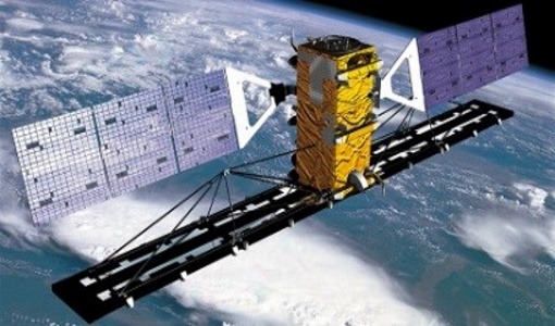
RADARSAT data on demand
In the framework of the Earthnet programme, ESA is distributing RADARSAT data on-demand to support EO science and research activities.
Event - Workshop
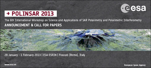
POLinSAR 2013
The objectives of the PolInSAR 2013 workshop were to present the latest studies and results of SAR polarimetry and polarimetric interferometry.
Event - Conference

IGARSS 2020
The main theme for the virtual 2020 IEEE International Geoscience and Remote Sensing Symposium (IGARSS) was "Remote Sensing: Global Perspectives for Local Solutions". The event gathered those engaged in the fields of geoscience and remote sensing.
Data - Announcement of Opportunity (Restrained)
Announcement of Opportunity for NoR
ESA invites submissions for the Network of Resources (NoR) call, which aims to support research, development and pre-commercial users to innovate their working practices, moving from a data download paradigm towards a 'bring the user to the data' paradigm.
Data - Project Proposal (Restrained)
PAZ Full Archive and New Tasking
PAZ Image Products can be acquired in eight image modes with flexible resolutions (from 1 m to 40 m) and scene sizes. Thanks to different polarimetric combinations and processing levels the delivered imagery can be tailored specifically to meet the requirements of the application. Available modes are: StripMap mode (SM): in single and dual polarisation: The ground swath is illuminated with a continuous train of pulses while the antenna beam is pointed to a fixed angle, both in elevation and in azimuth. ScanSAR mode (SC): in single polarisation: the swath width is increased in respect to the StripMap mode, it is composed of four different sub-swaths, which are obtained by antenna steering in elevation direction Wide ScanSAR mode (WS), in single polarisation: the usage of six sub-swaths allows to obtain a higher swath coverage product Spotlight modes: in single and dual polarisation: Spotlight modes take advantage of the beam steering capability in the azimuth plane to illuminate for a longer time the area of interest: a sensible improvement of the azimuth resolution is achieved at the expense of a shorter scene size. Spotlight mode (SL) is designed to maximise the azimuth scene extension at the expense of the spatial resolution, and High Resolution Spotlight mode (HS) is designed to maximize the spatial resolutions at the expense of the scene extension. Staring Spotlight mode (ST), in single polarisation: The virtual rotation point coincides with the center of the beam: the image length in the flight direction is constrained by the projection on-ground of the azimuth beamwidth and it leads to a target azimuth illumination time increment and to achieve the best azimuth resolution. There are two main classes of products: Spatially Enhanced products (SE): Designed with the target of maximize the spatial resolution in pixels with squared size, so the larger resolution value of azimuth or ground range determines the square pixel size, and the smaller resolution value is adjusted to this size and the corresponding reduction of the bandwidth is used for speckle reduction. Radiometrically Enhanced products (RE): Designed with the target of maximize the radiometry, so the range and azimuth resolutions are intentionally decreased to significantly reduce speckle by averaging several looks. The following geometric projections are offered: Single Look Slant Range Complex (SSC): Single look product of the focused radar signal: the pixels are spaced equidistant in azimuth and in slant range. No geocoding is available, no radiometric artifacts included. Product delivered in the DLR-defined binary COSAR format. The SSC product is intended for applications that require the full bandwidth and phase information, e.g. for SAR interferometry and polarimetry. Multi Look Ground Range Detected (MGD): Detected multi look product in GeoTiff format with reduced speckle and approximately square resolution cells on ground. The image coordinates are oriented along flight direction and along ground range; the pixel spacing is equidistant in azimuth and in ground range. A simple polynomial slant to ground projection is performed in range using a WGS84 ellipsoid and an average, constant terrain height parameter. No image rotation to a map coordinate system is performed and interpolation artifacts are thus avoided. Geocoded Ellipsoid Corrected (GEC): Multi look detected product in GeoTiff format. It is projected and re-sampled to the WGS84 reference ellipsoid assuming one average terrain height. No terrain correction performed. UTM is the standard projection, for polar regions UPS is applied. Enhanced Ellipsoid Corrected (EEC): Multi look detected product in GeoTiff format. It is projected and re-sampled to the WGS84 reference ellipsoid. The image distortions caused by varying terrain height are corrected using an external DEM; therefore the pixel localization in these products is highly accurate. UTM is the standard projection, for polar regions UPS is applied. StripMap Single StripMap Dual ScanSAR Wide ScanSAR Spotlight Single Spotlight Dual HR Spotlight Single HR Spotlight Dual Staring Spotlight Mode ID SM-S SM-D SC WS SL-S SL-D HS-S HS-D ST Polarizations HH, VV, HV, VH HH/VV, HH/HV, VV/VH HH, VV, HV, VH HH, VV, HV, VH HH, VV, HV, VH HH/VV, HH/HV, VV/VH HH, VV, HV, VH HH/VV, HH/HV, VV/VH HH, VV, HV, VH Scene size (Range x Azimuth) [km] 30 x 50 15 x 50 100 x 150 [273-196] x 208 10 x 10 10 x 10 10-6 x 5 (depending on incident angle) 10 x 5 [9-4.6] x [2.7-3.6] Range Resolution [m] MGD, GEC, EEC (SE)[Ground range] 2.99 - 3.52 at (45° - 20°) 6 N/A N/A 1.55 - 3.43 at (55° - 20°) 3.09 - 3.5 at (55° - 20°) 1 - 1.76 at (55° - 20°) 2 - 3.5 at (55° - 20°) 0.96 -1.78 at (45°- 20°) MGD, GEC, EEC (RE) [Ground range] 6.53 - 7.65 at (45° - 20°) 7.51 - 10.43 at (45° - 20°) 16.79 - 18.19 at (45° - 20°) 35 3.51 - 5.43 at (55° - 20°) 4.98 - 7.63 at (55° - 20°) 2.83 - 3.11 at (55° - 20°) 4 - 6.2 at (55° - 20°) 0.97 - 1.78 at (45°-20°) SSC[Slant range] 1.1 (150 MHz bandwidth) 1.7 (100 MHz bandwidth) 1.18 1.17 - 3.4 (depending on range bandwidth) 1.75 - 3.18 (depending on range bandwidth) 1.18 1.17 0.6 1.17 0.59 Azimuth Resolution [m] MGD, GEC, EEC (SE) 3.05 6.11 N/A N/A 1.56 - 2.9 at (55° - 20°) 3.53 1 - 1.49 at (55 °- 20°) 2.38 - 2.93 at (55° - 20°) 0.38 - 0.7 at (45°-20°) MGD, GEC, EEC (RE) 6.53 - 7.60 at (45° - 20°) 7.52 - 10.4 at (45° - 20°) 17.66 - 18.18 at (45° - 20°) 39 3.51 - 5.4 at (55° - 20°) 4.99 - 7.64 at (55° - 20°) 2.83 - 3.13 at (55° - 20°) 4 - 6.25 at (55° - 20°) 0.97 - 1.42 at (45°-20°) SSC 3.01 6.04 18.5 38.27 1.46 3.1 1.05 2.16 0.22 As per ESA policy, very high-resolution data over conflict areas cannot be provided.
Data - Fast Registration with approval (Restrained)
TerraSAR-X ESA archive
The TerraSAR-X ESA archive collection consists of TerraSAR-X and TanDEM-X products requested by ESA supported projects over their areas of interest around the world. The dataset regularly grows as ESA collects new products over the years. TerraSAR-X/TanDEM-X Image Products can be acquired in 6 image modes with flexible resolutions (from 0.25m to 40m) and scene sizes. Thanks to different polarimetric combinations and processing levels the delivered imagery can be tailored specifically to meet the requirements of the application. The following list delineates the characteristics of the SAR imaging modes that are disseminated under ESA Third Party Missions (TPM). StripMap (SM): Resolution 3 m, Scene size 30x50 km2 (up to 30x1650 km2) SpotLight (SL): Resolution 2 m, Scene size 10x10 km2 Staring SpotLight (ST): Resolution 0.25m, Scene size 4x3.7 km2 High Resolution SpotLight (HS): Resolution 1 m, Scene size 10x5 km2 ScanSAR (SC): Resolution 18 m, Scene size 100x150 km2 (up to 100x1650 km2) Wide ScanSAR (WS): Resolution 40 m, Scene size 270x200 km2 (up to 270x1500 km2) The following list briefly delineates the available processing levels for the TerraSAR-X dataset: SSC (Single Look Slant Range Complex) in DLR-defined COSAR binary format MGD (Multi Look Ground Range Detected) in GeoTiff format • GEC (Geocoded Ellipsoid Corrected) in GeoTiff format EEC (Enhanced Ellipsoid Corrected in GeoTiff format Spatial coverage: Check the spatial coverage of the collection on a map available on the Third Party Missions Dissemination Service. As per ESA policy, very high-resolution data over conflict areas cannot be provided.
Data - Project Proposal (Restrained)
TerraSAR-X/TanDEM-X full archive and tasking
TerraSAR-X/TanDEM-X full archive and new tasking products can be acquired in six image modes with flexible resolutions (from 0.25 m to 40 m) and scene sizes and are provided in different packages: Staring SpotLight (basic, Interferometric pack, and Maritime pack) High Resolution SpotLight (basic, Interferometric pack, and Maritime pack) SpotLight (basic, Interferometric pack, and Maritime pack) StripMap (basic, Interferometric pack, and Maritime pack) ScanSAR (basic and Maritime pack) Wide ScanSAR (basic and Maritime pack) Product Overview Products SAR-ST SAR-HS SAR-SL SAR-SM SAR-SC SAR-WS Instrument mode Staring Spotlight High Resolution SpotLight SpotLight StripMap ScanSAR Wide ScanSAR Available resolutions (up to) 0.25 m 1 m 2 m 3 m 18 m 40 m Scene size 4x3.7 km2 10x5 km2 10x10 km2 30x50 km2 (up to 30x1650) 100x150 km2 (up to 100x1650) 270x200 km2 (up to 270x1500) Available processing levels SSC (Single Look Slant Range Complex): azimuth - slant range (time domain) MGD (Multi Look Ground Range Detected): azimuth - ground range (without terrain correction) GEC (Geocoded Ellipsoid Corrected): map geometry with ellipsoidal corrections only (no terrain correction performed) EEC (Enhanced Ellipsoid Corrected): map geometry with terrain correction, using a DEM Format SSC: DLR-defined COSAR binary MGD: GeoTiff GEC: GeoTiff EEC: GeoTiff Spatial coverage Worldwide Interferometry package InSAR-ST, InSAR-HS, InSAR-SL, InSAR-SM Only SSC At least five ordered scenes within six months from first order N/A N/A Maritime Monitoring package MmSAR-ST, MmSAR-HS, MmSAR-SL, MmSAR-SM, MmSAR-SC, MmSAR-WS Only SSC, MGD, GEC At least 75% of the scene area is water More than five ordered scenes in three months The following WorldDEM products can be requested: Products Description WorldDEMcore WorldDEMcore is output of interferometric processing of StripMap data pairs without any post-processing WorldDEMTM WorldDEMTM is produced based on WorldDEMcore, representing the surface of the Earth (including buildings, infrastructure and vegetation). Hydrological consistency is ensured WorldDEM DTM In additional editing steps, WorldDEMTMis transformed into a Digital Terrain Model (DTM) representing bare Earth elevation WorldDEM Bundle Includes WorldDEMTM, WorldDEM DTM, and Quality Layers The main specifications of the WorldDEM products are: Horizontal Coordinate Reference System: World Geodetic System 1984 (WGS84-G1150) Vertical Coordinate Reference System: Earth Gravitational Model 2008 (EGM2008) Absolute Horizontal Accuracy: <6 m Vertical Accuracy: 2 m Relative, 4 m Absolute Quality Layers (including water body mask) can be requested as an option with the WorldDEM and WorldDEM DTM Auxiliary Layers are delivered together with the WorldDEMcore product As per ESA policy, very high-resolution data over conflict areas cannot be provided.