- All Categories (4568)
- Data (51)
- News (89)
- Missions (21)
- Events (45)
- Tools (17)
- Activities (17)
- Campaigns (9)
- Documents (4319)
DATA
Discover and download the Earth observation data you need from the broad catalogue of missions the European Space Agency operate and support.
Data - Sample Data (Open)
TerraSAR-X Sample Data
Download free TerraSAR-X sample datasets to preview products available for this mission.
Data - Sample Data (Open)
PAZ Sample Data
Download free PAZ sample datasets to preview products available for this mission.
Data - Sample Data (Open)
COSMO SkyMed Second Generation-SkyMed Sample Data
Download free COSMO-SkyMed Second Generation sample datasets to preview products available for this mission.
Data - Sample Data (Open)
WorldView-3 Sample Data
Download free WorldView-3 sample datasets to preview products available for this mission.
Data - Sample Data (Open)
COSMO-SkyMed Sample Data
Download free COSMO-SkyMed sample datasets to preview products available for this mission.
Data - Announcement of Opportunity (Restrained)
Announcement of Opportunity for NovaSAR-1
ESA is launching an Announcement of Opportunity for the international scientific community to access data from the NovaSAR-1 mission for science and EO-based applications development.
Data - Project Proposal (Restrained)
NovaSAR-1 new tasking
NovaSAR-1 new acquisition data are available in two baseline acquisition modes: Stripmap – provides the highest resolution of 6 metres with up to 20 km swath selected from a 150 km field of regard, available in single polarisation. ScanSAR – has a 20 - 30 metre resolution and up to 150 km swath. Available in single polarisation. Within each of the baseline modes there are a variety of mode options that vary according to ground range resolution, incidence angles, swath width and the number of looks: Acquisition Mode Polarisation Resolution (m) Swath Width (km) Incidence Angles Number of Looks Stripmap Single: HH 6 20 16.0 – 25.38° 3 (1 range, 3 azimuth) 13 – 20 21.29 – 31.2° Single: VV 6 20 16.0 – 25.38° 3 (1 range, 3 azimuth) 13 – 20 21.29 – 31.2° ScanSAR Single: HH 20 100 15.0 - 24.66° 4 (2 range, 2 azimuth) 50 24.51 - 28.94° Single: VV 20 100 15.0 – 24.66° 4 (2 range, 2 azimuth) 50 24.51 - 28.94° Single: HH 30 150 11.29 – 25.93° 4 (2 range, 2 azimuth) 55 27.35 - 32.01° Single: VV 30 150 11.29 – 25.93° 4 (2 range, 2 azimuth) 55 27.35 - 32.01° NovaSAR-1 data are provided as a Level 2 (ARD) product as standard, but the accompanying Level 1 data may also be requested. Level 1 – delivered as reconstructed, unprocessed instrument data at full resolution. Level 2 (ARD) – delivered as a processed product with applied radiometric and geometric corrections i.e. orthorectification and spatial registration: Geocoded Ellipsoid Corrected (GEC) – Maritime and ocean applications Geocoded Terrain Corrected (GTC) – Land applications and change detection Where available, associated automatic identification system (AIS) data may be requested alongside the NovaSAR-1 data products.
Data - EO Sign In Authentication (Open)
ICEYE ESA archive
The ICEYE ESA archive collection consists of ICEYE Level 1 products requested by ESA supported projects over their areas of interest around the world. The dataset regularly grows as ESA collects new products over the years. Three different modes are available: Spot: With a slant resolution of 50 cm in range by 25 cm in azimuth that translated into the ground generates a ground resolution of 1 m over an area of 5 km x 5 km. Due to multi-looking, speckle noise is significantly reduced Strip: The ground swath is 30 x 50 km2 and the ground range resolution is 3 m Scan: A large area (100 km x 100 km is acquired with ground resolution of 15 m). Two different processing levels: Single Look Complex (SLC): Level 1A geo-referenced product and stored in the satellite's native image acquisition geometry (the slant imaging plane) Ground Range Detected (GRD): Level 1B product; detected, multi-looked and projected to ground range using an Earth ellipsoid model; the image coordinates are oriented along the flight direction and along the ground range; no image rotation to a map coordinate system is performed, interpolation artefacts not introduced. The following table defines the offered product types: EO-SIP Product Type Mode Processing level XN_SM__SLC Strip Single Look Complex (SLC) - Level 1A XN_SM__GRD Strip Ground Range Detected (GRD) - Level 1B XN_SL__SLC Spot Single Look Complex (SLC) - Level 1A XN_SL__GRD Spot Ground Range Detected (GRD) - Level 1B XN_SR__GRD Scan Ground Range Detected (GRD) - Level 1B As per ESA policy, very high-resolution data over conflict areas cannot be provided.
Data - EO Sign In Authentication (Open)
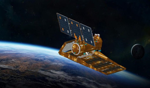
PAZ ESA archive
The PAZ ESA archive collection consists of PAZ Level 1 data previously requested by ESA supported projects over their areas of interest around the world and, as a consequence, the products are scattered and dispersed worldwide and in different time windows. The dataset regularly grows as ESA collects new products over the years. Available modes are: StripMap mode (SM): SSD less than 3 m for a scene 30 km x 50 km in single polarization or 15 km x 50 km in dual polarisation ScanSAR mode (SC): the scene is 100 x 150 km2, SSD less than 18 m in signle pol only Wide ScanSAR mode (WS): single polarisation only, with SS less than 40 m and scene size of 270 x 200 km2 Spotlight modes (SL): SSD less than 2 m for a scene 10 km x 10 km, both single and dual polarization are available High Resolution Spotlight mode (HS): in both single and dual polarisation, the scene is 10x5 km2, SSD less than 1 m Staring Spotlight mode (ST): SSD is 25 cm, the scene size is 4 x 4 km2, in single polarisation only. The available geometric projections are: Single Look Slant Range Complex (SSC): single look product, no geocoding, no radiometric artifact included, the pixel spacing is equidistant in azimuth and in ground range Multi Look Ground Range Detected (MGD): detected multi look product, simple polynomial slant-to-ground projection is performed in range, no image rotation to a map coordinate system is performed Geocoded Ellipsoid Corrected (GEC): multi look detected product, projected and re-sampled to the WGS84 reference ellipsoid with no terrain corrections Enhanced Ellipsoid Corrected (EEC): multi look detected product, projected and re-sampled to the WGS84 reference ellipsoid, the image distortions caused by varying terrain height are corrected using a DEM. The following table summarises the offered product types. EO-SIP product type Operation Mode Geometric Projection Geometric Projection PSP_SM_SSC Stripmap (SM) Single Look Slant Range Complex (SSC) PSP_SM_MGD Stripmap (SM) Multi Look Ground Range Detected (MGD) PSP_SM_GEC Stripmap (SM) Geocoded Ellipsoid Corrected (GEC) PSP_SM_EEC Stripmap (SM) Enhanced Ellipsoid Corrected (EEC) PSP_SC_MGD ScanSAR (SC) Multi Look Ground Range Detected (MGD) PSP_SC_GEC ScanSAR (SC) Multi Look Ground Range Detected (MGD) PSP_SC_EEC ScanSAR (SC) Geocoded Ellipsoid Corrected (GEC) PSP_SC_SSC ScanSAR (SC) Enhanced Ellipsoid Corrected (EEC) PSP_SL_SSC Spotlight (SL) Single Look Slant Range Complex (SSC) PSP_SL_MGD Spotlight (SL) Multi Look Ground Range Detected (MGD) PSP_SL_GEC Spotlight (SL) Geocoded Ellipsoid Corrected (GEC) PSP_SL_EEC Spotlight (SL) Enhanced Ellipsoid Corrected (EEC) PSP_HS_SSC High Resolution Spotlight (HS) Single Look Slant Range Complex (SSC) PSP_HS_MGD High Resolution Spotlight (HS) Multi Look Ground Range Detected (MGD) PSP_HS_GEC High Resolution Spotlight (HS) Geocoded Ellipsoid Corrected (GEC) PSP_HS_EEC High Resolution Spotlight (HS) Enhanced Ellipsoid Corrected (EEC) PSP_ST_SSC Staring Spotlight (ST) Single Look Slant Range Complex (SSC) PSP_ST_MGD Staring Spotlight (ST) Multi Look Ground Range Detected (MGD) PSP_ST_GEC Staring Spotlight (ST) Geocoded Ellipsoid Corrected (GEC) PSP_ST_EEC Staring Spotlight (ST) Enhanced Ellipsoid Corrected (EEC) PSP_WS_SSC Wide ScanSAR (WS) Single Look Slant Range Complex (SSC) PSP_WS_MGD Wide ScanSAR (WS) Multi Look Ground Range Detected (MGD) PSP_WS_GEC Wide ScanSAR (WS) Geocoded Ellipsoid Corrected (GEC) PSP_WS_EEC Wide ScanSAR (WS) Enhanced Ellipsoid Corrected (EEC) As per ESA policy, very high-resolution data over conflict areas cannot be provided.
Data - External Data (Restrained)
SAOCOM Europe data products
This collection provides access to the SAOCOM products acquired in the ASI Zone of Exclusivity, that correspond mainly to the European territory plus the international waters in front of North Africa and the Middle East, archived and catalogued in the ASI/CONAE dissemination system. ASI Zone of Exclusivity Platform SAOCOM 1A only (in future SAOCOM-1B will be added) Instrument L-Band SAR, 1.275 GHz Sensor mode STRIPMAP for data acquired at fixed azimuth steering (beam from S1 up to S10) TOPSAR for data acquired in ScanSAR like mode (Mode A, Mode B or Wide) Processing level L1A - SLC (single look complex, slat range), L1B - DI (detected image, ground range), L1C - GEC (geocoded on ellipsoid), L1D - GTC (geocoded on DEM) Resolution STRIPMAP: 10m TOPSAR Narrow: 30 - 50m TOPSAR WIDE: 50 - 100m Swath Width STRIPMAP: 20 - 40 km TOPSAR Narrow: 100 - 150 km TOPSAR Wide: 220 - 350 km Polarization Single polarization (HH or VV) only for STRIPMAP Double polarization (HHHV or VHVV) for both STRIPMAP and TOPSAR Quad Polarization for both STRIPMAP and TOPSAR
Data - Fast Registration with approval (Restrained)
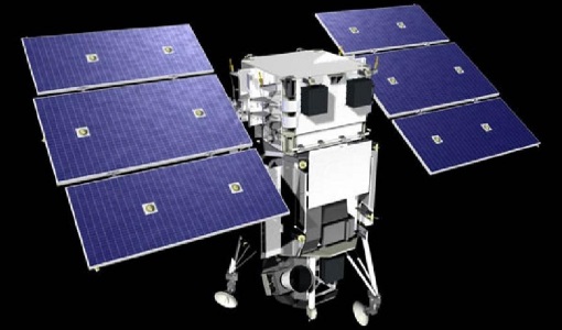
WorldView ESA archive
The WorldView ESA archive is composed of products acquired by WorldView-1, -2, -3 and -4 satellites and requested by ESA supported projects over their areas of interest around the world Panchromatic, 4-Bands, 8-Bands and SWIR products are part of the offer, with the resolution at Nadir depicted in the table. Band Combination Mission GSD Resolution at Nadir GSD Resolution (20° off nadir) Panchromatic WV-1 50 cm 55 cm WV-2 46 cm 52 cm WV-3 31 cm 34 cm WV-4 31 cm 34 cm 4-Bands WV-2 1.84 m 2.4 m WV-3 1.24 m 1.38 m WV-4 1.24 m 1.38 m 8-Bands WV-2 1.84 m 2.4 m WV-3 1.24 m 1.38 m SWIR WV-3 3.70 m 4.10 m The 4-Bands includes various options such as Multispectral (separate channel for Blue, Green, Red, NIR1), Pan-sharpened (Blue, Green, Red, NIR1), Bundle (separate bands for PAN, Blue, Green, Red, NIR1), Natural Colour (pan-sharpened Blue, Green, Red), Coloured Infrared (pan-sharpened Green, Red, NIR). The 8-Bands being an option from Multispectral (COASTAL, Blue, Green, Yellow, Red, Red EDGE, NIR1, NIR2) and Bundle (PAN, COASTAL, Blue, Green, Yellow, Red, Red EDGE, NIR1, NIR2). The processing levels are: Standard (2A): normalised for topographic relief View Ready Standard: ready for orthorectification (RPB files embedded) View Ready Stereo: collected in-track for stereo viewing and manipulation (not available for SWIR) Map Scale (Ortho) 1:12,000 Orthorectified: additional processing unnecessary Spatial coverage: Check the spatial coverage of the collection on a map available on the Third Party Missions Dissemination Service. The following table summarises the offered product types EO-SIP Product Type Band Combination Processing Level Missions WV6_PAN_2A Panchromatic (PAN) Standard/View Ready Standard WorldView-1 and 4 WV6_PAN_OR Panchromatic (PAN) View Ready Stereo WorldView-1 and 4 WV6_PAN_MP Panchromatic (PAN) Map Scale Ortho WorldView-1 and 4 WV1_PAN__2A Panchromatic (PAN) Standard/View Ready Standard WorldView-2 and 3 WV1_PAN__OR Panchromatic (PAN) View Ready Stereo WorldView-2 and 3 WV1_PAN__MP Panchromatic (PAN) Map Scale Ortho WorldView-2 and 3 WV1_4B__2A 4-Band (4B) Standard/View Ready Standard WorldView-2, 3 and 4 WV1_4B__OR 4-Band (4B) View Ready Stereo WorldView-2, 3 and 4 WV1_4B__MP 4-Band (4B) Map Scale Ortho WorldView-2, 3 and 4 WV1_8B_2A 8-Band (8B) Standard/View Ready Standard WorldView-2 and 3 WV1_8B_OR 8-Band (8B) View Ready Stereo WorldView-2 and 3 WV1_8B_MP 8-Band (8B) Map Scale Ortho WorldView-2 and 3 WV1_S8B__2A SWIR Standard/View Ready Standard WorldView-3 WV1_S8B__MP SWIR Map Scale Ortho WorldView-3 As per ESA policy, very high-resolution imagery of conflict areas cannot be provided.
Data - Data Description
Envisat ASAR AP Co- and Cross-polar L0 [ASA_APC/APH/APV_0P]
The ASAR Alternating Polarization Mode Level 0 (Co-polar and Cross-polar H and V) products contain time-ordered Annotated Instrument Source Packets (AISPs) corresponding to one of the three possible polarisation combinations: HH & HV, VV & VH and HH & VV, respectively. The echo samples in the AISPs have been compressed to 4 bits/sample using FBAQ. This is a high-rate, narrow swath mode, so data is only acquired for partial orbit segments. There are two co-registered images per acquisition and may be from one of seven different image swaths. The Level 0 product was produced systematically for all data acquired within this mode. Data Size: 56-100 km across track x 100 km along track. There are three AP Mode Level 0 products: ASA_APH_0P: The Cross-polar H Level 0 product corresponds to the polarisation combination HH/HV. ASA_APV_0P: The Cross-polar V Level 0 product corresponds to the polarisation combination VV/VH. ASA_APC_0P: The Co-polar Level 0 product corresponds to the polarisation combination HH/VV= H and H received/V transmit and V received.
Data - Fast Registration with approval (Restrained)
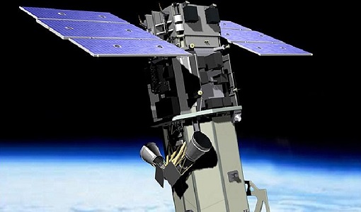
RADARSAT-2 ESA archive
The RADARSAT-2 ESA archive collection consists of RADARSAT-2 products requested by ESA supported projects over their areas of interest around the world. The dataset regularly grows as ESA collects new products over the years. Following Beam modes are available: Standard, Wide Swath, Fine Resolution, Extended Low Incidence, Extended High Incidence, ScanSAR Narrow and ScanSAR Wide. Standard Beam Mode allows imaging over a wide range of incidence angles with a set of image quality characteristics which provides a balance between fine resolution and wide coverage, and between spatial and radiometric resolutions. Standard Beam Mode operates with any one of eight beams, referred to as S1 to S8, in single and dual polarisation . The nominal incidence angle range covered by the full set of beams is 20 degrees (at the inner edge of S1) to 52 degrees (at the outer edge of S8). Each individual beam covers a nominal ground swath of 100 km within the total standard beam accessibility swath of more than 500 km. Beam Mode Product Nominal Resolution (metres) Nominal Pixel Spacing Range x Azimuth (metres) Resolution Range x Azimuth (metres) Nominal Scene Size Range x Azimuth (kilometres) Range of Angle of Incidence (degrees) Number of Looks Range x Azimuth Polarisations Options Standard SLC 25 8.0 or 11.8 x 5.1 9.0 or 13.5 x 7.7 100 x 100 20 - 52 1 x 1 Single Pol HH or VV or HV or VH - or - Dual HH + HV or VV + VH SGX 8.0 x 8.0 26.8 - 17.3 x 24.7 1 x 4 SGF 12.5 x 12.5 SSG, SPG Wide Swath Beam Mode allows imaging of wider swaths than Standard Beam Mode, but at the expense of slightly coarser spatial resolution. The three Wide Swath beams, W1, W2 and W3, provide coverage of swaths of approximately 170 km, 150 km and 130 km in width respectively, and collectively span a total incidence angle range from 20 degrees to 45 degrees. Polarisation can be single and dual. Beam Mode Product Nominal Resolution (metres) Nominal Pixel Spacing Range x Azimuth (metres) Resolution Range x Azimuth (metres) Nominal Scene Size Range x Azimuth (kilometres) Range of Angle of Incidence (degrees) Number of Looks Range x Azimuth Polarisations Options Wide SLC 30 11.8 x 5.1 13.5 x 7.7 150 x 150 20 - 45 1 x 1 Single: Pol HH or VV or HV or VH - or - Dual: HH + HV or VV + VH SGX 10 x 10 40.0 - 19.2 x 24.7 1 x 4 SGF 12.5 x 12.5 SSG, SPG Fine Resolution Beam Mode is intended for applications which require finer spatial resolution. Products from this beam mode have a nominal ground swath of 50 km. Nine Fine Resolution physical beams, F23 to F21, and F1 to F6 are available to cover the incidence angle range from 30 to 50 degrees. For each of these beams, the swath can optionally be centred with respect to the physical beam or it can be shifted slightly to the near or far range side. Thanks to these additional swath positioning choices, overlaps of more than 50% are provided between adjacent swaths. RADARSAT-2 can operate in single and dual polarisation for this beam mode. Beam Mode Product Nominal resolution (metres) Nominal Pixel Spacing Range x Azimuth (metres) Resolution Range x Azimuth (metres) Nominal Scene Size Range x Azimuth (kilometres) Range of Angle of Incidence (degrees) Number of Looks Range x Azimuth Polarisations Options Fine SLC 8 4.7 x 5.1 5.2 x 7.7 50 x 50 30 - 50 1 x 1 Single: Pol HH or VV or HV or VH - or - Dual: HH + HV or VV + VH SGX 3.13 x 3.13 10.4 - 6.8 x 7.7 1 x 1 SGF 6.25 x 6.25 SSG, SPG In the Extended Low Incidence Beam Mode, a single Extended Low Incidence Beam, EL1, is provided for imaging in the incidence angle range from 10 to 23 degrees with a nominal ground swath coverage of 170 km. Some minor degradation of image quality can be expected due to operation of the antenna beyond its optimum scan angle range. Only single polarisation is available. Beam Mode Product Nominal resolution (metres) Nominal Pixel Spacing Range x Azimuth (metres) Resolution Range x Azimuth (metres) Nominal Scene Size Range x Azimuth (kilometres) Range of Angle of Incidence (degrees) Number of Looks Range x Azimuth Polarisations Options Extended Low SLC 25 8.0 x 5.1 9.0 x 7.7 170 x 170 10 - 23 1 x 1 Single: HH SGX 10.0 x 10.0 52.7 - 23.3 x 24.7 1 x 4 SGF 12.5 x 12.5 SSG, SPG In the Extended High Incidence Beam Mode, six Extended High Incidence Beams, EH1 to EH6, are available for imaging in the 49 to 60 degree incidence angle range. Since these beams operate outside the optimum scan angle range of the SAR antenna, some degradation of image quality, becoming progressively more severe with increasing incidence angle, can be expected when compared with the Standard Beams. Swath widths are restricted to a nominal 80 km for the inner three beams, and 70 km for the outer beams. Only single polarisation available. Beam Mode Product Nominal resolution (metres) Nominal Pixel Spacing Range x Azimuth (metres) Resolution Range x Azimuth (metres) Nominal Scene Size Range x Azimuth (kilometres) Range of Angle of Incidence (degrees) Number of Looks Range x Azimuth Polarisations Options Extended High SLC 25 11.8 x 5.1 13.5 x 7.7 75 x 75 49 - 60 1 x 1 Single Pol HH SGX 8.0 x 8.0 18.2 - 15.9 x 24.7 1 x 4 SGF 12.5 x 12.5 SSG, SPG ScanSAR Narrow Beam Mode provides coverage of a ground swath approximately double the width of the Wide Swath Beam Mode swaths. Two swath positions with different combinations of physical beams can be used: SCNA, which uses physical beams W1 and W2, and SCNB, which uses physical beams W2, S5, and S6. Both options provide coverage of swath widths of about 300 km. The SCNA combination provides coverage over the incidence angle range from 20 to 39 degrees. The SCNB combination provides coverage over the incidence angle range 31 to 47 degrees. RADARSAT-2 can operate in single and dual polarisation for this beam mode. Beam Mode Product Nominal resolution (metres) Nominal Pixel Spacing Range x Azimuth (metres) Resolution Range x Azimuth (metres) Nominal Scene Size Range x Azimuth (kilometres) Range of Angle of Incidence (degrees) Number of Looks Range x Azimuth Polarisations Options ScanSAR Narrow SCN, SCF, SCS 20 25 x 25 81 - 38 x 40 - 70 300 x 300 20 - 46 2 x 2 Single Co or Cross: HH or VV or HV or VH - or - Dual: HH + HV or VV + VH ScanSAR Wide Beam Mode provides coverage of a ground swath approximately triple the width of the Wide Swath Beam Mode swaths. Two swath positions with different combinations of physical beams can be used: SCWA, which uses physical beams W1, W2, W3, and S7, and SCWB, which uses physical beams W1, W2, S5 and S6. The SCWA combination allows imaging of a swath of more than 500 km covering an incidence angle range of 20 to 49 degrees. The SCWB combination allows imaging of a swath of more than 450 km covering the incidence angle. Polarisation can be single and dual. Beam Mode Product Nominal resolution (metres) Nominal Pixel Spacing Range x Azimuth (metres) Resolution Range x Azimuth (metres) Nominal Scene Size Range x Azimuth (kilometres) Range of Angle of Incidence (degrees) Number of Looks Range x Azimuth Polarisations Options ScanSAR Wide SCW, SCF, SCS 100 50 x 50 163 - 73 x 78 - 106 500 x 500 20 - 49 4 x 2 Single Co or Cross: HH or VV or HV or VH - or - Dual: HH + HV or VV + VH These are the different products : SLC (Single Look Complex): Amplitude and phase information is preserved. Data is in slant range. Georeferenced and aligned with the satellite track SGF (Path Image): Data is converted to ground range and may be multi-look processed. Scene is oriented in direction of orbit path. Georeferenced and aligned with the satellite track. SGX (Path Image Plus): Same as SGF except processed with refined pixel spacing as needed to fully encompass the image data bandwidths. Georeferenced and aligned with the satellite track SSG(Map Image): Image is geocorrected to a map projection. SPG (Precision Map Image): Image is geocorrected to a map projection. Ground control points (GCP) are used to improve positional accuracy. SCN(ScanSAR Narrow)/SCF(ScanSAR Wide) : ScanSAR Narrow/Wide beam mode product with original processing options and metadata fields (for backwards compatibility only). Georeferenced and aligned with the satellite track SCF (ScanSAR Fine): ScanSAR product equivalent to SGF with additional processing options and metadata fields. Georeferenced and aligned with the satellite track SCS(ScanSAR Sampled) : Same as SCF except with finer sampling. Georeferenced and aligned with the satellite track. Spatial coverage: Check the spatial coverage of the collection on a map available on the Third Party Missions Dissemination Service.
Data - Announcement of Opportunity (Restrained)

Announcement of Opportunity for G-POD
ESA is offering all scientists the possibility to perform bulk processing and/or validation of their own algorithms exploiting the large ESA Earth-observation archive.
Data - Project Proposal (Restrained)
ICEYE full archive and tasking
ICEYE full archive and new tasking products are available in Strip, Spot, SLEA (Spot Extended Area), Scan, and Dwell modes: Strip instrument mode: the ground swath is illuminated with a continuous sequence of pulses while the antenna beam is fixed in its orientation. This results in a long image strip parallel to the flight direction: the transmitted pulse bandwidth is adjusted to always achieve a ground range resolution of 3 m Spot instrument mode: the radar beam is steered to illuminate a fixed point to increase the illumination time, resulting in an extended Synthetic aperture length, which improves the azimuth resolution. Spot mode uses a 300 MHz pulse bandwidth and provides a slant plane image with a resolution of 0.5 m (range) by 0.25 m (azimuth); when translated into the ground, the products has 1 m resolution covering an area of 5 km x 5 km. Due to multi-looking, speckle noise is significantly reduced As an evolution of Spot mode, SLEA (Spot Extended Area) products are available with the same resolution of Spot data but a scene size of 15 km x 15 km Scan Instrument mode: the phased array antenna is used to create multiple beams in the elevation direction which allows to acquire a large area (100km x 100km) with resolution better than 15m. To achieve the finest image quality of its Scan image, ICEYE employs a TOPSAR technique, which brings major benefits over the quality of the images obtained with conventional SCANSAR imaging. With the 2-dimensional electronic beam steering, TOPSAR ensures the maximum radar power distribution in the scene, providing uniform image quality. Dwell mode: with the satellite staring at the same location for up to 25 seconds, Dwell mode is a very long Spot mode SAR collection. This yields a very fine azimuth resolution and highly-reduced speckle. The 25 second collection time allows the acquired image stack to be reconstructed as a video to give insight into the movement of objects. Two different processing levels can be requested: Single Look Complex (SLC): Single Look Complex (SLC) Level 1a products consist of focused SAR data geo-referenced using orbit and attitude data from the satellite and the scenes are stored in the satellite's native image acquisition geometry which is the slant-range-by-azimuth imaging plane and with zero-Doppler SAR coordinates. The pixels are spaced equidistant in azimuth and in slant range. The products include a single look in each dimension using the full transmit signal bandwidth and consist of complex magnitude value samples preserving both amplitude and phase information. No radiometric artefacts induced by spatial resampling or geocoding. The product is provided in Hierarchical Data Format (HDF5) plus a xml file with selected metadata Ground Range Detected (GRD): Ground Range Detected (GRD) Level 1b products consist of focused SAR data that has been detected, multi-looked and projected to ground range using an Earth ellipsoid model. The image coordinates are oriented along the flight direction and along the ground range. Pixel values represent detected magnitude, the phase information is lost. The resulting product has approximately square spatial resolution pixels and square pixel spacing with reduced speckle due to the multi-look processing at the cost of worse spatial resolution. No image rotation to a map coordinate system has been performed and interpolation artefacts are thus avoided. The product is provided in GeoTiff plus a xml file with selected metadata. Strip Spot SLEA Scan Dwell Ground range resolution (GRD) 3 m 1 m 1 m 15 m 1 Ground azimuth resolution (GRD) 3 m 1 m 1 m 15 m 1 Slant range resolution (SLC) 0.5 m - 2.5 m 0.5 m 0.5 m 0.5 m Slant azimuth resolution (SLC) 3 m 0.25 m 1 m 0.05 m Scene size (W x L) 30 x 50 km2 5 x 5 km2 15 x 15 km2 100 x 100 km2 5 x 5 km2 Incident angle 15 - 30° 20 - 35° 20 - 35° 21 - 29° 20 - 35° Polarisation VV All details about the data provision, data access conditions and quota assignment procedure are described in the ICEYE Terms of Applicability. In addition, ICEYE has released a public catalogue that contains nearly 18,000 thumbnails under a creative common license of radar images acquired with ICEYE's SAR satellite constellation all around the world from 2019 until October 2020. Access to the catalogue requires registration. As per ESA policy, very high-resolution data over conflict areas cannot be provided.
Data - Project Proposal (Restrained)
PAZ Full Archive and New Tasking
PAZ Image Products can be acquired in eight image modes with flexible resolutions (from 1 m to 40 m) and scene sizes. Thanks to different polarimetric combinations and processing levels the delivered imagery can be tailored specifically to meet the requirements of the application. Available modes are: StripMap mode (SM): in single and dual polarisation: The ground swath is illuminated with a continuous train of pulses while the antenna beam is pointed to a fixed angle, both in elevation and in azimuth. ScanSAR mode (SC): in single polarisation: the swath width is increased in respect to the StripMap mode, it is composed of four different sub-swaths, which are obtained by antenna steering in elevation direction Wide ScanSAR mode (WS), in single polarisation: the usage of six sub-swaths allows to obtain a higher swath coverage product Spotlight modes: in single and dual polarisation: Spotlight modes take advantage of the beam steering capability in the azimuth plane to illuminate for a longer time the area of interest: a sensible improvement of the azimuth resolution is achieved at the expense of a shorter scene size. Spotlight mode (SL) is designed to maximise the azimuth scene extension at the expense of the spatial resolution, and High Resolution Spotlight mode (HS) is designed to maximize the spatial resolutions at the expense of the scene extension. Staring Spotlight mode (ST), in single polarisation: The virtual rotation point coincides with the center of the beam: the image length in the flight direction is constrained by the projection on-ground of the azimuth beamwidth and it leads to a target azimuth illumination time increment and to achieve the best azimuth resolution. There are two main classes of products: Spatially Enhanced products (SE): Designed with the target of maximize the spatial resolution in pixels with squared size, so the larger resolution value of azimuth or ground range determines the square pixel size, and the smaller resolution value is adjusted to this size and the corresponding reduction of the bandwidth is used for speckle reduction. Radiometrically Enhanced products (RE): Designed with the target of maximize the radiometry, so the range and azimuth resolutions are intentionally decreased to significantly reduce speckle by averaging several looks. The following geometric projections are offered: Single Look Slant Range Complex (SSC): Single look product of the focused radar signal: the pixels are spaced equidistant in azimuth and in slant range. No geocoding is available, no radiometric artifacts included. Product delivered in the DLR-defined binary COSAR format. The SSC product is intended for applications that require the full bandwidth and phase information, e.g. for SAR interferometry and polarimetry. Multi Look Ground Range Detected (MGD): Detected multi look product in GeoTiff format with reduced speckle and approximately square resolution cells on ground. The image coordinates are oriented along flight direction and along ground range; the pixel spacing is equidistant in azimuth and in ground range. A simple polynomial slant to ground projection is performed in range using a WGS84 ellipsoid and an average, constant terrain height parameter. No image rotation to a map coordinate system is performed and interpolation artifacts are thus avoided. Geocoded Ellipsoid Corrected (GEC): Multi look detected product in GeoTiff format. It is projected and re-sampled to the WGS84 reference ellipsoid assuming one average terrain height. No terrain correction performed. UTM is the standard projection, for polar regions UPS is applied. Enhanced Ellipsoid Corrected (EEC): Multi look detected product in GeoTiff format. It is projected and re-sampled to the WGS84 reference ellipsoid. The image distortions caused by varying terrain height are corrected using an external DEM; therefore the pixel localization in these products is highly accurate. UTM is the standard projection, for polar regions UPS is applied. StripMap Single StripMap Dual ScanSAR Wide ScanSAR Spotlight Single Spotlight Dual HR Spotlight Single HR Spotlight Dual Staring Spotlight Mode ID SM-S SM-D SC WS SL-S SL-D HS-S HS-D ST Polarizations HH, VV, HV, VH HH/VV, HH/HV, VV/VH HH, VV, HV, VH HH, VV, HV, VH HH, VV, HV, VH HH/VV, HH/HV, VV/VH HH, VV, HV, VH HH/VV, HH/HV, VV/VH HH, VV, HV, VH Scene size (Range x Azimuth) [km] 30 x 50 15 x 50 100 x 150 [273-196] x 208 10 x 10 10 x 10 10-6 x 5 (depending on incident angle) 10 x 5 [9-4.6] x [2.7-3.6] Range Resolution [m] MGD, GEC, EEC (SE)[Ground range] 2.99 - 3.52 at (45° - 20°) 6 N/A N/A 1.55 - 3.43 at (55° - 20°) 3.09 - 3.5 at (55° - 20°) 1 - 1.76 at (55° - 20°) 2 - 3.5 at (55° - 20°) 0.96 -1.78 at (45°- 20°) MGD, GEC, EEC (RE) [Ground range] 6.53 - 7.65 at (45° - 20°) 7.51 - 10.43 at (45° - 20°) 16.79 - 18.19 at (45° - 20°) 35 3.51 - 5.43 at (55° - 20°) 4.98 - 7.63 at (55° - 20°) 2.83 - 3.11 at (55° - 20°) 4 - 6.2 at (55° - 20°) 0.97 - 1.78 at (45°-20°) SSC[Slant range] 1.1 (150 MHz bandwidth) 1.7 (100 MHz bandwidth) 1.18 1.17 - 3.4 (depending on range bandwidth) 1.75 - 3.18 (depending on range bandwidth) 1.18 1.17 0.6 1.17 0.59 Azimuth Resolution [m] MGD, GEC, EEC (SE) 3.05 6.11 N/A N/A 1.56 - 2.9 at (55° - 20°) 3.53 1 - 1.49 at (55 °- 20°) 2.38 - 2.93 at (55° - 20°) 0.38 - 0.7 at (45°-20°) MGD, GEC, EEC (RE) 6.53 - 7.60 at (45° - 20°) 7.52 - 10.4 at (45° - 20°) 17.66 - 18.18 at (45° - 20°) 39 3.51 - 5.4 at (55° - 20°) 4.99 - 7.64 at (55° - 20°) 2.83 - 3.13 at (55° - 20°) 4 - 6.25 at (55° - 20°) 0.97 - 1.42 at (45°-20°) SSC 3.01 6.04 18.5 38.27 1.46 3.1 1.05 2.16 0.22 As per ESA policy, very high-resolution data over conflict areas cannot be provided.
Data - Fast Registration with approval (Restrained)
ALOS PALSAR products
The dataset contains all ESA acquisitions over the ADEN zone (Europe, Africa and the Middle East) plus some products received from JAXA over areas of interest around the world. Further information on ADEN zones can be found in this technical note. ALOS PALSAR products are available in following modes: Fine Beam Single polarisation (FBS), single polarisation (HH or VV), swath 40-70 km, resolution 10 m, temporal coverage from 02/05/2006 to 30/03/2011 Fine Beam Double polarisation (FBD), double polarisation (HH/HV or VV/VH), swath 40-70 km, resolution 10 m, temporal coverage from 02/05/2006 to 30/03/2011 Polarimetry mode (PLR), with four polarisations simultaneously: swath 30 km, resolution 30 m, temporal coverage from 26/08/2006 to 14/04/2011 ScanSAR Burst mode 1 (WB1), single polarisation: swath 250-350 km, resolution 100 m, temporal coverage from 12/06/2006 to 21/04/2011. Following processing levels are available: RAW (Level 1.0): Raw data generated by every downlink segment and every band. Divided into an equivalent size to one scene SLC (Level 1.1): Slant range single look complex product. Not available for WB1 GDH (Level 1.5): Ground range Detected, Normal resolution product GEC (Level 1.5): Geocoded product. The table summarises the ALOS PALSAR offer. Instrument mode Product type Processing level description JAXA processing level equivalent Fine Beam Single polarisation (HH or VV) FBS_RAW_0P Raw data generated by every downlink segment and every band. Divided into an equivalent size to one scene 1.0 FBS_GDH_1P Ground range Detected, Normal resolution product 1.5 FBS_GEC_1P Geocoded product 1.5 FBS_SLC_1P Slant range single look complex product 1.1 Fine Beam Double polarisation (HH/HV or VV/VH) FBD_RAW_0P Raw data generated by every downlink segment and every band. Divided into an equivalent size to one scene 1.0 FBD_GDH_1P Ground range Detected, Normal resolution product 1.5 FBD_GEC_1P Geocoded product 1.5 FBD_SLC_1P Slant range single look complex product 1.1 Polarimetry mode (4 polarisation) PLR_RAW_0P Raw data generated by every downlink segment and every band. Divided into an equivalent size to one scene 1.0 PLR_GDH_1P Ground range Detected, Normal resolution product 1.5 PLR_GEC_1P Geocoded product 1.5 PLR_SLC_1P Slant range single look complex product 1.1 ScanSAR Burst mode 1 (single polarisation) WB1_RAW_0P Raw data generated by every downlink segment and every band. Divided into an equivalent size to one scene 1.0 WB1_GDH_1P Ground range Detected, Normal resolution product 1.5 WB1_GEC_1P Geocoded product 1.5
Data - Project Proposal (Restrained)
TerraSAR-X/TanDEM-X full archive and tasking
TerraSAR-X/TanDEM-X full archive and new tasking products can be acquired in six image modes with flexible resolutions (from 0.25 m to 40 m) and scene sizes and are provided in different packages: Staring SpotLight (basic, Interferometric pack, and Maritime pack) High Resolution SpotLight (basic, Interferometric pack, and Maritime pack) SpotLight (basic, Interferometric pack, and Maritime pack) StripMap (basic, Interferometric pack, and Maritime pack) ScanSAR (basic and Maritime pack) Wide ScanSAR (basic and Maritime pack) Product Overview Products SAR-ST SAR-HS SAR-SL SAR-SM SAR-SC SAR-WS Instrument mode Staring Spotlight High Resolution SpotLight SpotLight StripMap ScanSAR Wide ScanSAR Available resolutions (up to) 0.25 m 1 m 2 m 3 m 18 m 40 m Scene size 4x3.7 km2 10x5 km2 10x10 km2 30x50 km2 (up to 30x1650) 100x150 km2 (up to 100x1650) 270x200 km2 (up to 270x1500) Available processing levels SSC (Single Look Slant Range Complex): azimuth - slant range (time domain) MGD (Multi Look Ground Range Detected): azimuth - ground range (without terrain correction) GEC (Geocoded Ellipsoid Corrected): map geometry with ellipsoidal corrections only (no terrain correction performed) EEC (Enhanced Ellipsoid Corrected): map geometry with terrain correction, using a DEM Format SSC: DLR-defined COSAR binary MGD: GeoTiff GEC: GeoTiff EEC: GeoTiff Spatial coverage Worldwide Interferometry package InSAR-ST, InSAR-HS, InSAR-SL, InSAR-SM Only SSC At least five ordered scenes within six months from first order N/A N/A Maritime Monitoring package MmSAR-ST, MmSAR-HS, MmSAR-SL, MmSAR-SM, MmSAR-SC, MmSAR-WS Only SSC, MGD, GEC At least 75% of the scene area is water More than five ordered scenes in three months The following WorldDEM products can be requested: Products Description WorldDEMcore WorldDEMcore is output of interferometric processing of StripMap data pairs without any post-processing WorldDEMTM WorldDEMTM is produced based on WorldDEMcore, representing the surface of the Earth (including buildings, infrastructure and vegetation). Hydrological consistency is ensured WorldDEM DTM In additional editing steps, WorldDEMTMis transformed into a Digital Terrain Model (DTM) representing bare Earth elevation WorldDEM Bundle Includes WorldDEMTM, WorldDEM DTM, and Quality Layers The main specifications of the WorldDEM products are: Horizontal Coordinate Reference System: World Geodetic System 1984 (WGS84-G1150) Vertical Coordinate Reference System: Earth Gravitational Model 2008 (EGM2008) Absolute Horizontal Accuracy: <6 m Vertical Accuracy: 2 m Relative, 4 m Absolute Quality Layers (including water body mask) can be requested as an option with the WorldDEM and WorldDEM DTM Auxiliary Layers are delivered together with the WorldDEMcore product As per ESA policy, very high-resolution data over conflict areas cannot be provided.
Data - Fast Registration with approval (Restrained)
TerraSAR-X ESA archive
The TerraSAR-X ESA archive collection consists of TerraSAR-X and TanDEM-X products requested by ESA supported projects over their areas of interest around the world. The dataset regularly grows as ESA collects new products over the years. TerraSAR-X/TanDEM-X Image Products can be acquired in 6 image modes with flexible resolutions (from 0.25m to 40m) and scene sizes. Thanks to different polarimetric combinations and processing levels the delivered imagery can be tailored specifically to meet the requirements of the application. The following list delineates the characteristics of the SAR imaging modes that are disseminated under ESA Third Party Missions (TPM). StripMap (SM): Resolution 3 m, Scene size 30x50 km2 (up to 30x1650 km2) SpotLight (SL): Resolution 2 m, Scene size 10x10 km2 Staring SpotLight (ST): Resolution 0.25m, Scene size 4x3.7 km2 High Resolution SpotLight (HS): Resolution 1 m, Scene size 10x5 km2 ScanSAR (SC): Resolution 18 m, Scene size 100x150 km2 (up to 100x1650 km2) Wide ScanSAR (WS): Resolution 40 m, Scene size 270x200 km2 (up to 270x1500 km2) The following list briefly delineates the available processing levels for the TerraSAR-X dataset: SSC (Single Look Slant Range Complex) in DLR-defined COSAR binary format MGD (Multi Look Ground Range Detected) in GeoTiff format • GEC (Geocoded Ellipsoid Corrected) in GeoTiff format EEC (Enhanced Ellipsoid Corrected in GeoTiff format Spatial coverage: Check the spatial coverage of the collection on a map available on the Third Party Missions Dissemination Service. As per ESA policy, very high-resolution data over conflict areas cannot be provided.
Data - Project Proposal (Restrained)
WorldView-3 full archive and tasking
WorldView-3 high resolution optical products are available as part of the Maxar Standard Satellite Imagery products from the QuickBird, WorldView-1/-2/-3/-4, and GeoEye-1 satellites. All details about the data provision, data access conditions and quota assignment procedure are described into the Terms of Applicability available in Resources section. In particular, WorldView-3 offers archive and tasking panchromatic products up to 0.31m GSD resolution, 4-Bands/8-Bands products up to 1.24 m GSD resolution, and SWIR products up to 3.70 m GSD resolution. Band Combination Data Processing Level Resolution High Res Optical: Panchromatic and 4-bands Standard(2A)/View Ready Standard (OR2A) 15 cm HD, 30 cm HD, 30 cm, 40 cm, 50/60 cm View Ready Stereo 30 cm, 40 cm, 50/60 cm Map Ready (Ortho) 1:12.000 Orthorectified 15 cm HD, 30 cm HD, 30 cm, 40 cm, 50/60 cm High Res Optical: 8-bands Standard(2A)/View Ready Standard (OR2A) 30 cm, 40 cm, 50/60 cm View Ready Stereo 30 cm, 40 cm, 50/60 cm Map Ready (Ortho) 1:12.000 Orthorectified 30 cm, 40 cm, 50/60 cm High Res Optical: SWIR Standard(2A)/View Ready Standard (OR2A) 3.7 m or 7.5 m (depending on the collection date) Map Ready (Ortho) 1:12.000 Orthorectified 4-Bands being an optional from: 4-Band Multispectral (BLUE, GREEN, RED, NIR1) 4-Band Pan-sharpened (BLUE, GREEN, RED, NIR1) 4-Band Bundle (PAN, BLUE, GREEN, RED, NIR1) 3-Bands Natural Colour (pan-sharpened BLUE, GREEN, RED) 3-Band Colored Infrared (pan-sharpened GREEN, RED, NIR1) 8-Bands being an optional from: 8-Band Multispectral (COASTAL, BLUE, GREEN, YELLOW, RED, RED EDGE, NIR1, NIR2) 8-Band Bundle (PAN, COASTAL, BLUE, GREEN, YELLOW, RED, RED EDGE, NIR1, NIR2) Native 30 cm and 50/60 cm resolution products are processed with MAXAR HD Technology to generate respectively the 15 cm HD and 30 cm HD products: the initial special resolution (GSD) is unchanged but the HD technique increases the number of pixels and improves the visual clarity achieving aesthetically refined imagery with precise edges and well reconstructed details. As per ESA policy, very high-resolution imagery of conflict areas cannot be provided.