- All Categories (4345)
- Data (49)
- News (126)
- Missions (7)
- Events (45)
- Tools (14)
- Activities (12)
- Campaigns (7)
- Documents (4085)
DATA
Discover and download the Earth observation data you need from the broad catalogue of missions the European Space Agency operate and support.
Data - Announcement of Opportunity (Restrained)
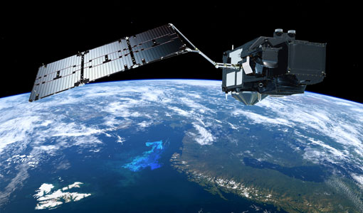
Announcement of Opportunity for S3VT (Sentinel-3 Validation Team)
In the framework of a Copernicus collaborative agreement ESA and EUMETSAT invite interested groups and individuals to support the Sentinel-3 Validation Team (S3VT).
Data - EO Sign In Authentication (Open)
PAZ ESA archive
The PAZ ESA archive collection consists of PAZ Level 1 data previously requested by ESA supported projects over their areas of interest around the world and, as a consequence, the products are scattered and dispersed worldwide and in different time windows. The dataset regularly grows as ESA collects new products over the years. Available modes are: StripMap mode (SM): SSD less than 3 m for a scene 30 km x 50 km in single polarization or 15 km x 50 km in dual polarisation ScanSAR mode (SC): the scene is 100 x 150 km2, SSD less than 18 m in signle pol only Wide ScanSAR mode (WS): single polarisation only, with SS less than 40 m and scene size of 270 x 200 km2 Spotlight modes (SL): SSD less than 2 m for a scene 10 km x 10 km, both single and dual polarization are available High Resolution Spotlight mode (HS): in both single and dual polarisation, the scene is 10x5 km2, SSD less than 1 m Staring Spotlight mode (ST): SSD is 25 cm, the scene size is 4 x 4 km2, in single polarisation only. The available geometric projections are: Single Look Slant Range Complex (SSC): single look product, no geocoding, no radiometric artifact included, the pixel spacing is equidistant in azimuth and in ground range Multi Look Ground Range Detected (MGD): detected multi look product, simple polynomial slant-to-ground projection is performed in range, no image rotation to a map coordinate system is performed Geocoded Ellipsoid Corrected (GEC): multi look detected product, projected and re-sampled to the WGS84 reference ellipsoid with no terrain corrections Enhanced Ellipsoid Corrected (EEC): multi look detected product, projected and re-sampled to the WGS84 reference ellipsoid, the image distortions caused by varying terrain height are corrected using a DEM. The following table summarises the offered product types. EO-SIP product type Operation Mode Geometric Projection Geometric Projection PSP_SM_SSC Stripmap (SM) Single Look Slant Range Complex (SSC) PSP_SM_MGD Stripmap (SM) Multi Look Ground Range Detected (MGD) PSP_SM_GEC Stripmap (SM) Geocoded Ellipsoid Corrected (GEC) PSP_SM_EEC Stripmap (SM) Enhanced Ellipsoid Corrected (EEC) PSP_SC_MGD ScanSAR (SC) Multi Look Ground Range Detected (MGD) PSP_SC_GEC ScanSAR (SC) Multi Look Ground Range Detected (MGD) PSP_SC_EEC ScanSAR (SC) Geocoded Ellipsoid Corrected (GEC) PSP_SC_SSC ScanSAR (SC) Enhanced Ellipsoid Corrected (EEC) PSP_SL_SSC Spotlight (SL) Single Look Slant Range Complex (SSC) PSP_SL_MGD Spotlight (SL) Multi Look Ground Range Detected (MGD) PSP_SL_GEC Spotlight (SL) Geocoded Ellipsoid Corrected (GEC) PSP_SL_EEC Spotlight (SL) Enhanced Ellipsoid Corrected (EEC) PSP_HS_SSC High Resolution Spotlight (HS) Single Look Slant Range Complex (SSC) PSP_HS_MGD High Resolution Spotlight (HS) Multi Look Ground Range Detected (MGD) PSP_HS_GEC High Resolution Spotlight (HS) Geocoded Ellipsoid Corrected (GEC) PSP_HS_EEC High Resolution Spotlight (HS) Enhanced Ellipsoid Corrected (EEC) PSP_ST_SSC Staring Spotlight (ST) Single Look Slant Range Complex (SSC) PSP_ST_MGD Staring Spotlight (ST) Multi Look Ground Range Detected (MGD) PSP_ST_GEC Staring Spotlight (ST) Geocoded Ellipsoid Corrected (GEC) PSP_ST_EEC Staring Spotlight (ST) Enhanced Ellipsoid Corrected (EEC) PSP_WS_SSC Wide ScanSAR (WS) Single Look Slant Range Complex (SSC) PSP_WS_MGD Wide ScanSAR (WS) Multi Look Ground Range Detected (MGD) PSP_WS_GEC Wide ScanSAR (WS) Geocoded Ellipsoid Corrected (GEC) PSP_WS_EEC Wide ScanSAR (WS) Enhanced Ellipsoid Corrected (EEC) As per ESA policy, very high-resolution data over conflict areas cannot be provided.
Data - Data Description
Envisat ASAR AP Co- and Cross-polar L0 [ASA_APC/APH/APV_0P]
The ASAR Alternating Polarization Mode Level 0 (Co-polar and Cross-polar H and V) products contain time-ordered Annotated Instrument Source Packets (AISPs) corresponding to one of the three possible polarisation combinations: HH & HV, VV & VH and HH & VV, respectively. The echo samples in the AISPs have been compressed to 4 bits/sample using FBAQ. This is a high-rate, narrow swath mode, so data is only acquired for partial orbit segments. There are two co-registered images per acquisition and may be from one of seven different image swaths. The Level 0 product was produced systematically for all data acquired within this mode. Data Size: 56-100 km across track x 100 km along track. There are three AP Mode Level 0 products: ASA_APH_0P: The Cross-polar H Level 0 product corresponds to the polarisation combination HH/HV. ASA_APV_0P: The Cross-polar V Level 0 product corresponds to the polarisation combination VV/VH. ASA_APC_0P: The Co-polar Level 0 product corresponds to the polarisation combination HH/VV= H and H received/V transmit and V received.
Data - Fast Registration with approval (Restrained)
RADARSAT-2 ESA archive
The RADARSAT-2 ESA archive collection consists of RADARSAT-2 products requested by ESA supported projects over their areas of interest around the world. The dataset regularly grows as ESA collects new products over the years. Following Beam modes are available: Standard, Wide Swath, Fine Resolution, Extended Low Incidence, Extended High Incidence, ScanSAR Narrow and ScanSAR Wide. Standard Beam Mode allows imaging over a wide range of incidence angles with a set of image quality characteristics which provides a balance between fine resolution and wide coverage, and between spatial and radiometric resolutions. Standard Beam Mode operates with any one of eight beams, referred to as S1 to S8, in single and dual polarisation . The nominal incidence angle range covered by the full set of beams is 20 degrees (at the inner edge of S1) to 52 degrees (at the outer edge of S8). Each individual beam covers a nominal ground swath of 100 km within the total standard beam accessibility swath of more than 500 km. Beam Mode Product Nominal Resolution (metres) Nominal Pixel Spacing Range x Azimuth (metres) Resolution Range x Azimuth (metres) Nominal Scene Size Range x Azimuth (kilometres) Range of Angle of Incidence (degrees) Number of Looks Range x Azimuth Polarisations Options Standard SLC 25 8.0 or 11.8 x 5.1 9.0 or 13.5 x 7.7 100 x 100 20 - 52 1 x 1 Single Pol HH or VV or HV or VH - or - Dual HH + HV or VV + VH SGX 8.0 x 8.0 26.8 - 17.3 x 24.7 1 x 4 SGF 12.5 x 12.5 SSG, SPG Wide Swath Beam Mode allows imaging of wider swaths than Standard Beam Mode, but at the expense of slightly coarser spatial resolution. The three Wide Swath beams, W1, W2 and W3, provide coverage of swaths of approximately 170 km, 150 km and 130 km in width respectively, and collectively span a total incidence angle range from 20 degrees to 45 degrees. Polarisation can be single and dual. Beam Mode Product Nominal Resolution (metres) Nominal Pixel Spacing Range x Azimuth (metres) Resolution Range x Azimuth (metres) Nominal Scene Size Range x Azimuth (kilometres) Range of Angle of Incidence (degrees) Number of Looks Range x Azimuth Polarisations Options Wide SLC 30 11.8 x 5.1 13.5 x 7.7 150 x 150 20 - 45 1 x 1 Single: Pol HH or VV or HV or VH - or - Dual: HH + HV or VV + VH SGX 10 x 10 40.0 - 19.2 x 24.7 1 x 4 SGF 12.5 x 12.5 SSG, SPG Fine Resolution Beam Mode is intended for applications which require finer spatial resolution. Products from this beam mode have a nominal ground swath of 50 km. Nine Fine Resolution physical beams, F23 to F21, and F1 to F6 are available to cover the incidence angle range from 30 to 50 degrees. For each of these beams, the swath can optionally be centred with respect to the physical beam or it can be shifted slightly to the near or far range side. Thanks to these additional swath positioning choices, overlaps of more than 50% are provided between adjacent swaths. RADARSAT-2 can operate in single and dual polarisation for this beam mode. Beam Mode Product Nominal resolution (metres) Nominal Pixel Spacing Range x Azimuth (metres) Resolution Range x Azimuth (metres) Nominal Scene Size Range x Azimuth (kilometres) Range of Angle of Incidence (degrees) Number of Looks Range x Azimuth Polarisations Options Fine SLC 8 4.7 x 5.1 5.2 x 7.7 50 x 50 30 - 50 1 x 1 Single: Pol HH or VV or HV or VH - or - Dual: HH + HV or VV + VH SGX 3.13 x 3.13 10.4 - 6.8 x 7.7 1 x 1 SGF 6.25 x 6.25 SSG, SPG In the Extended Low Incidence Beam Mode, a single Extended Low Incidence Beam, EL1, is provided for imaging in the incidence angle range from 10 to 23 degrees with a nominal ground swath coverage of 170 km. Some minor degradation of image quality can be expected due to operation of the antenna beyond its optimum scan angle range. Only single polarisation is available. Beam Mode Product Nominal resolution (metres) Nominal Pixel Spacing Range x Azimuth (metres) Resolution Range x Azimuth (metres) Nominal Scene Size Range x Azimuth (kilometres) Range of Angle of Incidence (degrees) Number of Looks Range x Azimuth Polarisations Options Extended Low SLC 25 8.0 x 5.1 9.0 x 7.7 170 x 170 10 - 23 1 x 1 Single: HH SGX 10.0 x 10.0 52.7 - 23.3 x 24.7 1 x 4 SGF 12.5 x 12.5 SSG, SPG In the Extended High Incidence Beam Mode, six Extended High Incidence Beams, EH1 to EH6, are available for imaging in the 49 to 60 degree incidence angle range. Since these beams operate outside the optimum scan angle range of the SAR antenna, some degradation of image quality, becoming progressively more severe with increasing incidence angle, can be expected when compared with the Standard Beams. Swath widths are restricted to a nominal 80 km for the inner three beams, and 70 km for the outer beams. Only single polarisation available. Beam Mode Product Nominal resolution (metres) Nominal Pixel Spacing Range x Azimuth (metres) Resolution Range x Azimuth (metres) Nominal Scene Size Range x Azimuth (kilometres) Range of Angle of Incidence (degrees) Number of Looks Range x Azimuth Polarisations Options Extended High SLC 25 11.8 x 5.1 13.5 x 7.7 75 x 75 49 - 60 1 x 1 Single Pol HH SGX 8.0 x 8.0 18.2 - 15.9 x 24.7 1 x 4 SGF 12.5 x 12.5 SSG, SPG ScanSAR Narrow Beam Mode provides coverage of a ground swath approximately double the width of the Wide Swath Beam Mode swaths. Two swath positions with different combinations of physical beams can be used: SCNA, which uses physical beams W1 and W2, and SCNB, which uses physical beams W2, S5, and S6. Both options provide coverage of swath widths of about 300 km. The SCNA combination provides coverage over the incidence angle range from 20 to 39 degrees. The SCNB combination provides coverage over the incidence angle range 31 to 47 degrees. RADARSAT-2 can operate in single and dual polarisation for this beam mode. Beam Mode Product Nominal resolution (metres) Nominal Pixel Spacing Range x Azimuth (metres) Resolution Range x Azimuth (metres) Nominal Scene Size Range x Azimuth (kilometres) Range of Angle of Incidence (degrees) Number of Looks Range x Azimuth Polarisations Options ScanSAR Narrow SCN, SCF, SCS 20 25 x 25 81 - 38 x 40 - 70 300 x 300 20 - 46 2 x 2 Single Co or Cross: HH or VV or HV or VH - or - Dual: HH + HV or VV + VH ScanSAR Wide Beam Mode provides coverage of a ground swath approximately triple the width of the Wide Swath Beam Mode swaths. Two swath positions with different combinations of physical beams can be used: SCWA, which uses physical beams W1, W2, W3, and S7, and SCWB, which uses physical beams W1, W2, S5 and S6. The SCWA combination allows imaging of a swath of more than 500 km covering an incidence angle range of 20 to 49 degrees. The SCWB combination allows imaging of a swath of more than 450 km covering the incidence angle. Polarisation can be single and dual. Beam Mode Product Nominal resolution (metres) Nominal Pixel Spacing Range x Azimuth (metres) Resolution Range x Azimuth (metres) Nominal Scene Size Range x Azimuth (kilometres) Range of Angle of Incidence (degrees) Number of Looks Range x Azimuth Polarisations Options ScanSAR Wide SCW, SCF, SCS 100 50 x 50 163 - 73 x 78 - 106 500 x 500 20 - 49 4 x 2 Single Co or Cross: HH or VV or HV or VH - or - Dual: HH + HV or VV + VH These are the different products : SLC (Single Look Complex): Amplitude and phase information is preserved. Data is in slant range. Georeferenced and aligned with the satellite track SGF (Path Image): Data is converted to ground range and may be multi-look processed. Scene is oriented in direction of orbit path. Georeferenced and aligned with the satellite track. SGX (Path Image Plus): Same as SGF except processed with refined pixel spacing as needed to fully encompass the image data bandwidths. Georeferenced and aligned with the satellite track SSG(Map Image): Image is geocorrected to a map projection. SPG (Precision Map Image): Image is geocorrected to a map projection. Ground control points (GCP) are used to improve positional accuracy. SCN(ScanSAR Narrow)/SCF(ScanSAR Wide) : ScanSAR Narrow/Wide beam mode product with original processing options and metadata fields (for backwards compatibility only). Georeferenced and aligned with the satellite track SCF (ScanSAR Fine): ScanSAR product equivalent to SGF with additional processing options and metadata fields. Georeferenced and aligned with the satellite track SCS(ScanSAR Sampled) : Same as SCF except with finer sampling. Georeferenced and aligned with the satellite track. Spatial coverage: Check the spatial coverage of the collection on a map available on the Third Party Missions Dissemination Service.
Data - Announcement of Opportunity (Restrained)
Announcement of Opportunity for NoR
ESA invites submissions for the Network of Resources (NoR) call, which aims to support research, development and pre-commercial users to innovate their working practices, moving from a data download paradigm towards a 'bring the user to the data' paradigm.
Data - Announcement of Opportunity (Restrained)
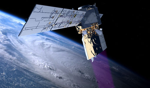
Announcement of Opportunity for Aeolus Cal/Val
An Announcement of Opportunity call is open for the Aeolus mission. Scientists, new groups and individuals are invited to participate in Aeolus Cal/Val throughout the mission lifetime.
Data - Project Proposal (Restrained)
PAZ Full Archive and New Tasking
PAZ Image Products can be acquired in eight image modes with flexible resolutions (from 1 m to 40 m) and scene sizes. Thanks to different polarimetric combinations and processing levels the delivered imagery can be tailored specifically to meet the requirements of the application. Available modes are: StripMap mode (SM): in single and dual polarisation: The ground swath is illuminated with a continuous train of pulses while the antenna beam is pointed to a fixed angle, both in elevation and in azimuth. ScanSAR mode (SC): in single polarisation: the swath width is increased in respect to the StripMap mode, it is composed of four different sub-swaths, which are obtained by antenna steering in elevation direction Wide ScanSAR mode (WS), in single polarisation: the usage of six sub-swaths allows to obtain a higher swath coverage product Spotlight modes: in single and dual polarisation: Spotlight modes take advantage of the beam steering capability in the azimuth plane to illuminate for a longer time the area of interest: a sensible improvement of the azimuth resolution is achieved at the expense of a shorter scene size. Spotlight mode (SL) is designed to maximise the azimuth scene extension at the expense of the spatial resolution, and High Resolution Spotlight mode (HS) is designed to maximize the spatial resolutions at the expense of the scene extension. Staring Spotlight mode (ST), in single polarisation: The virtual rotation point coincides with the center of the beam: the image length in the flight direction is constrained by the projection on-ground of the azimuth beamwidth and it leads to a target azimuth illumination time increment and to achieve the best azimuth resolution. There are two main classes of products: Spatially Enhanced products (SE): Designed with the target of maximize the spatial resolution in pixels with squared size, so the larger resolution value of azimuth or ground range determines the square pixel size, and the smaller resolution value is adjusted to this size and the corresponding reduction of the bandwidth is used for speckle reduction. Radiometrically Enhanced products (RE): Designed with the target of maximize the radiometry, so the range and azimuth resolutions are intentionally decreased to significantly reduce speckle by averaging several looks. The following geometric projections are offered: Single Look Slant Range Complex (SSC): Single look product of the focused radar signal: the pixels are spaced equidistant in azimuth and in slant range. No geocoding is available, no radiometric artifacts included. Product delivered in the DLR-defined binary COSAR format. The SSC product is intended for applications that require the full bandwidth and phase information, e.g. for SAR interferometry and polarimetry. Multi Look Ground Range Detected (MGD): Detected multi look product in GeoTiff format with reduced speckle and approximately square resolution cells on ground. The image coordinates are oriented along flight direction and along ground range; the pixel spacing is equidistant in azimuth and in ground range. A simple polynomial slant to ground projection is performed in range using a WGS84 ellipsoid and an average, constant terrain height parameter. No image rotation to a map coordinate system is performed and interpolation artifacts are thus avoided. Geocoded Ellipsoid Corrected (GEC): Multi look detected product in GeoTiff format. It is projected and re-sampled to the WGS84 reference ellipsoid assuming one average terrain height. No terrain correction performed. UTM is the standard projection, for polar regions UPS is applied. Enhanced Ellipsoid Corrected (EEC): Multi look detected product in GeoTiff format. It is projected and re-sampled to the WGS84 reference ellipsoid. The image distortions caused by varying terrain height are corrected using an external DEM; therefore the pixel localization in these products is highly accurate. UTM is the standard projection, for polar regions UPS is applied. StripMap Single StripMap Dual ScanSAR Wide ScanSAR Spotlight Single Spotlight Dual HR Spotlight Single HR Spotlight Dual Staring Spotlight Mode ID SM-S SM-D SC WS SL-S SL-D HS-S HS-D ST Polarizations HH, VV, HV, VH HH/VV, HH/HV, VV/VH HH, VV, HV, VH HH, VV, HV, VH HH, VV, HV, VH HH/VV, HH/HV, VV/VH HH, VV, HV, VH HH/VV, HH/HV, VV/VH HH, VV, HV, VH Scene size (Range x Azimuth) [km] 30 x 50 15 x 50 100 x 150 [273-196] x 208 10 x 10 10 x 10 10-6 x 5 (depending on incident angle) 10 x 5 [9-4.6] x [2.7-3.6] Range Resolution [m] MGD, GEC, EEC (SE)[Ground range] 2.99 - 3.52 at (45° - 20°) 6 N/A N/A 1.55 - 3.43 at (55° - 20°) 3.09 - 3.5 at (55° - 20°) 1 - 1.76 at (55° - 20°) 2 - 3.5 at (55° - 20°) 0.96 -1.78 at (45°- 20°) MGD, GEC, EEC (RE) [Ground range] 6.53 - 7.65 at (45° - 20°) 7.51 - 10.43 at (45° - 20°) 16.79 - 18.19 at (45° - 20°) 35 3.51 - 5.43 at (55° - 20°) 4.98 - 7.63 at (55° - 20°) 2.83 - 3.11 at (55° - 20°) 4 - 6.2 at (55° - 20°) 0.97 - 1.78 at (45°-20°) SSC[Slant range] 1.1 (150 MHz bandwidth) 1.7 (100 MHz bandwidth) 1.18 1.17 - 3.4 (depending on range bandwidth) 1.75 - 3.18 (depending on range bandwidth) 1.18 1.17 0.6 1.17 0.59 Azimuth Resolution [m] MGD, GEC, EEC (SE) 3.05 6.11 N/A N/A 1.56 - 2.9 at (55° - 20°) 3.53 1 - 1.49 at (55 °- 20°) 2.38 - 2.93 at (55° - 20°) 0.38 - 0.7 at (45°-20°) MGD, GEC, EEC (RE) 6.53 - 7.60 at (45° - 20°) 7.52 - 10.4 at (45° - 20°) 17.66 - 18.18 at (45° - 20°) 39 3.51 - 5.4 at (55° - 20°) 4.99 - 7.64 at (55° - 20°) 2.83 - 3.13 at (55° - 20°) 4 - 6.25 at (55° - 20°) 0.97 - 1.42 at (45°-20°) SSC 3.01 6.04 18.5 38.27 1.46 3.1 1.05 2.16 0.22 As per ESA policy, very high-resolution data over conflict areas cannot be provided.
Data - Announcement of Opportunity (Restrained)
CLOSED - Announcement of Opportunity for Spire data
An opportunity for scientists and researchers to access Spire data.
Data - EO Sign In Authentication (Open)

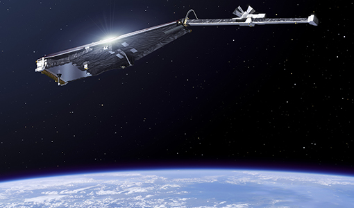
VT GOCE Data
This collection contains the VT GOCE software and associated data set needed to run the software that is used for GOCE data visualisation.
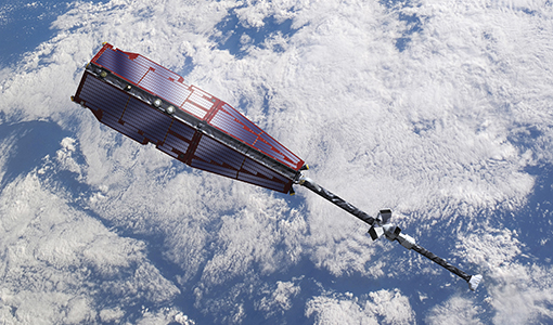
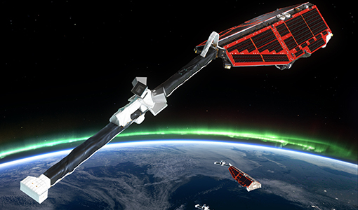
Data - Open access (Open)
Swarm Core
Spherical harmonic model of the main (core) field and its temporal variation.
Data - Open access (Open)
Swarm Ionosphere/Magnetosphere
Spherical harmonic model of the large-scale magnetospheric field and its Earth-induced counterpart, spherical harmonic model of the daily geomagnetic variation at middle latitudes and low latitudes, Ionospheric bubble index, ionospheric total electron content, ionosphericfield-aligned currents, dayside ionospheric equatorial electric field, ionospheric plasma density and plasma irregularities.
Data - Open access (Open)
Swarm Level 2 daily
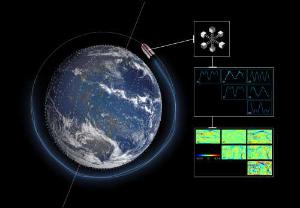
The Swarm Level 1b data products are the corrected and formatted output from each of the three Swarm satellites. By a complex assimilation of these individual satellite measurements into one set of products for the satellite constellation, the Swarm Level 2 Processor ensures a very significant improvement of the quality of the final scientific data products.
Data - Open access (Open)
Swarm Geodesy/Gravity
Monthly gravity field of the Earth, non-gravitational accelerations.
Data - Open access (Open)
Swarm Level 1B
The Level 1b products of the Swarm mission contains time-series of quality-screen, calibrated, and corrected measurements given in physical, SI units in geo-localized reference frames. Level 1b products are provided individually for each of the three satellites Swarm A, Swarm B, and Swarm C on a daily basis.
Data - Open access (Open)
Swarm Space Weather
Environmental conditions in Earth's magnetosphere, ionosphere and thermosphere due to the solar activity that drive the Sun-Earth interactions.
Data - Open access (Open)
Swarm Level 2 longterm
The Swarm Level 2 Long Term data products are the corrected and formatted output from each of the three Swarm satellites. By a complex assimilation of these individual satellite measurements into one set of products for the satellite constellation, the Swarm Level 2 Processor ensures a very significant improvement of the quality of the final scientific data products.