- All Categories (186)
- Data (11)
- News (25)
- Missions (2)
- Events (14)
- Tools (10)
- Activities (2)
- Campaigns (1)
- Documents (121)
DATA
Discover and download the Earth observation data you need from the broad catalogue of missions the European Space Agency operate and support.
Data - Fast Registration with approval (Restrained)
ALOS PRISM L1C
This collection provides access to the ALOS-1 PRISM (Panchromatic Remote-sensing Instrument for Stereo Mapping) OB1 L1C data acquired by ESA stations (Kiruna, Maspalomas, Matera, Tromsoe) in the ADEN zone, in addition to worldwide data requested by European scientists. The ADEN zone was the area belonging to the European Data node and covered both the European and African continents, a large part of Greenland and the Middle East. The full mission archive is included in this collection, though with gaps in spatial coverage outside of the ADEN zone. With respect to the L1B collection, only scenes acquired in sensor mode with a Cloud Coverage score lower than 70% and a sea percentage lower than 80% are published: Orbits: from 2768 to 27604 Path (corresponds to JAXA track number): from 1 to 665 Row (corresponds to JAXA scene centre frame number): from 310 to 6790. The L1C processing strongly improve accuracy compared to L1B1 from several tenths of metres in L1B1 (~40 m of northing geolocation error for Forward views and ~10-20 m for easting errors) to some metres in L1C scenes (< 10 m both in north and easting errors). The collection contains only the PSM_OB1_1C EO-SIP product type, using data from PRISM operating in OB1 mode with three views (Nadir, Forward, and Backward) at 35 km wide. Most of the products contain all three views, but the Nadir view is always available and is used for the frame number identification. All views are packaged together; each view, in CEOS format, is stored in a directory named according to the JAXA view ID naming convention.
Data - Fast Registration with approval (Restrained)
ALOS PRISM L1C European Coverage Cloud Free
This collection is composed of a subset of ALOS-1 PRISM (Panchromatic Remote-sensing Instrument for Stereo Mapping) OB1 L1C products from the ALOS PRISM L1C collection (DOI: 10.57780/AL1-ff3877f) which have been chosen so as to provide a cloud-free coverage over Europe. 70% of the scenes contained within the collection have a cloud cover percentage of 0%, while the remaining 30% of the scenes have a cloud cover percentage of no more than 20%. The collection is composed of PSM_OB1_1C EO-SIP products, with the PRISM sensor operating in OB1 mode with three views (Nadir, Forward and Backward) at 35 km width.
Data - Fast Registration with approval (Restrained)
ALOS AVNIR-2 L1C
This collection provides access to the ALOS-1 AVNIR-2 (Advanced Visible and Near Infrared Radiometer type 2) L1C data acquired by ESA stations in the ADEN zone plus some worldwide data requested by European scientists. The ADEN zone was the area belonging to the European Data node and covered both the European and African continents, a large part of Greenland and the Middle East. The full mission archive is included in this collection, though with gaps in spatial coverage Time window: from 2006-04-28 to 2011-04-20 Orbits: from 1375 to 27898 Path (corresponds to JAXA track number): from 1 to 670 Row (corresponds to JAXA scene centre frame number): from 370 to 5230. One single Level 1C product type is offered for the OBS instrument mode: AV2_OBS_1C. The Level 1C product is a multispectral image (three bands in VIS and one in NIR) in GEOTIFF format with 10 m resolution.
Data - Fast Registration with approval (Restrained)
ALOS PRISM L1B
This collection provides access to the ALOS-1 PRISM (Panchromatic Remote-sensing Instrument for Stereo Mapping) L1b data acquired by ESA stations in the ADEN zone, in addition to worldwide data requested by European scientists. The ADEN zone was the area belonging to the European Data node and covered both the European and African continents, a large part of Greenland and the Middle East. The full mission archive is included in this collection, though with gaps in spatial coverage outside of the ADEN zone. The full mission is covered, though with gaps outside of the ADEN zone: Time window: from 2006-07-09 to 2011-03-31 Orbits: from 2425 to 24189 Path (corresponds to JAXA track number): from 1 to 668 Row (corresponds to JAXA scene centre frame number): from 55 to 7185. Two different Level 1B product types (Panchromatic images in VIS-NIR bands, 2.5 m resolution at nadir) are offered, one for each available sensor mode: PSM_OB1_11 -> Composed of up to three views; Nadir, Forward and Backward at 35 km swath PSM_OB2_11 -> Composed of up to two views; Nadir view at 70 km width and Backward view at 35 km width. All ALOS PRISM EO-SIP products have, at least, the Nadir view which is used for the frame number identification. All views are packaged together; each view, in CEOS format, is stored in a directory named according to the view ID according to the JAXA naming convention.
Data - Fast Registration with approval (Restrained)
ALOS PALSAR products
The dataset contains all ESA acquisitions over the ADEN zone (Europe, Africa and the Middle East) plus some products received from JAXA over areas of interest around the world. Further information on ADEN zones can be found in this technical note. ALOS PALSAR products are available in following modes: Fine Beam Single polarisation (FBS), single polarisation (HH or VV), swath 40-70 km, resolution 10 m, temporal coverage from 02/05/2006 to 30/03/2011 Fine Beam Double polarisation (FBD), double polarisation (HH/HV or VV/VH), swath 40-70 km, resolution 10 m, temporal coverage from 02/05/2006 to 30/03/2011 Polarimetry mode (PLR), with four polarisations simultaneously: swath 30 km, resolution 30 m, temporal coverage from 26/08/2006 to 14/04/2011 ScanSAR Burst mode 1 (WB1), single polarisation: swath 250-350 km, resolution 100 m, temporal coverage from 12/06/2006 to 21/04/2011. Following processing levels are available: RAW (Level 1.0): Raw data generated by every downlink segment and every band. Divided into an equivalent size to one scene SLC (Level 1.1): Slant range single look complex product. Not available for WB1 GDH (Level 1.5): Ground range Detected, Normal resolution product GEC (Level 1.5): Geocoded product. The table summarises the ALOS PALSAR offer. Instrument mode Product type Processing level description JAXA processing level equivalent Fine Beam Single polarisation (HH or VV) FBS_RAW_0P Raw data generated by every downlink segment and every band. Divided into an equivalent size to one scene 1.0 FBS_GDH_1P Ground range Detected, Normal resolution product 1.5 FBS_GEC_1P Geocoded product 1.5 FBS_SLC_1P Slant range single look complex product 1.1 Fine Beam Double polarisation (HH/HV or VV/VH) FBD_RAW_0P Raw data generated by every downlink segment and every band. Divided into an equivalent size to one scene 1.0 FBD_GDH_1P Ground range Detected, Normal resolution product 1.5 FBD_GEC_1P Geocoded product 1.5 FBD_SLC_1P Slant range single look complex product 1.1 Polarimetry mode (4 polarisation) PLR_RAW_0P Raw data generated by every downlink segment and every band. Divided into an equivalent size to one scene 1.0 PLR_GDH_1P Ground range Detected, Normal resolution product 1.5 PLR_GEC_1P Geocoded product 1.5 PLR_SLC_1P Slant range single look complex product 1.1 ScanSAR Burst mode 1 (single polarisation) WB1_RAW_0P Raw data generated by every downlink segment and every band. Divided into an equivalent size to one scene 1.0 WB1_GDH_1P Ground range Detected, Normal resolution product 1.5 WB1_GEC_1P Geocoded product 1.5
Data - Data Description
TropForest - ALOS, GEOSAT-1 & KOMPSAT-2 optical coverages over tropical forests
The objective of the ESA TropForest project was to create a harmonised geo-database of ready-to-use satellite imagery to support 2010 global forest assessment performed by the Joint Research Centre (JRC) of the European Commission and by the Food and Agriculture Organization (FAO). Assessments for year 2010 were essential for building realistic deforestation benchmark rates at global to regional levels. To reach this objective, the project aimed to create a harmonised ortho-rectified/pre-processed imagery geo-database based on satellite data acquisitions (ALOS AVNIR-2, GEOSAT-1 SLIM6, KOMPSAT-2 MSC) performed during year 2009 and 2010, for the Tropical Latin America (excluding Mexico) and for the Tropical South and Southeast Asia (excluding China), resulting in 1971 sites located at 1° x 1° geographical lat/long intersections. The project finally delivered 1866 sites (94.7% of target) due to cloud coverages too high for missing sites. Spatial coverage: Check the spatial coverage of the collection on a map available on the Third Party Missions Dissemination Service.
Data - Project Proposal (Restrained)
RADARSAT-1 & 2 full archive and tasking
RADARSAT-1 products The Standard beam mode operates with any one of seven beam positions, referred to as S1 to S7. The nominal incidence angle range covered by the full set of Standard beams is from 20 degrees (at the inner edge of S1) to 49 degrees (at the outer edge of S7). Each individual beam covers a minimum ground swath of 100 km within the total 500 km accessibility swath of the full set of Standard beams. The nominal spatial resolution in the range direction is 26 m for S1 at near range to 20 m for S7 at far range. The nominal azimuth resolution is the same, 27 m, for all beam positions. The Wide beam modes are similar to the Standard beams except that the swath width achieved by this beam is 150 km rather than 100 km. As a result, only three Wide beams, W1, W2 and W3 are necessary to provide coverage of almost all of the 500 km swath range. They provide comparable resolution to the standard beam mode, though the increased ground swath coverage is obtained at the expense of a slight reduction in overall image quality. In the Fine beam mode the nominal azimuth resolution is 8.4 m, with range resolution 9.1 m to 7.8 m from F1 to F5. Since the radar operates with a higher sampling rate in this mode than in any of the other beam mode, the ground swath coverage has to be reduced to approximately 50 km in order to keep the downlink signal within its allocated bandwidth. Originally, five Fine beam positions, F1 to F5, were available to cover the far range of the swath with an incidence angle range from 37 to 47 degrees. By modifying timing parameters, 10 new positions have been added with offset ground coverage. Each original Fine beam position can either be shifted closer to or further away from Nadir. In Extended High beam mode six positions, EH1 to EH6, are available for collection of data in the 49 to 60 degree incidence angle range. Since this beam mode operates outside the optimum scan angle range of the SAR antenna, some minor degradation of image quality can be expected when compared with the Standard beam mode. Swath widths are restricted to a nominal 80 km for the inner three positions, and 70 km for the outer three positions. In Extended Low beam mode one position, EL1, is provided for imaging in the incidence angle range 10 to 23 degrees with nominal ground swath coverage of 170 km. As with the Extended High beam mode, some minor degradation of image quality can be expected due to operation of the antenna beyond its optimum elevation angle range. In ScanSAR mode, combinations of two, three or four single beams are used during data collection. Each beam is selected sequentially so that data is collected from a wider swath than possible with a single beam. The beam switching rates are chosen to ensure at least one "look" at the Earth's surface for each beam within the along track illumination time or dwell time of the antenna beam. In practice, the radar beam switching is adjusted to provide two looks per beam. The beam multiplexing inherent in ScanSAR operation reduces the effective sampling rate within each of the component beams; hence the increased swath coverage is obtained at the expense of spatial resolution. The ScanSAR Narrow mode combines two beams (incidence angle range of 20 to 39 degrees) or three beams (incidence angle from 31 to 46 degrees) and provides coverage of a nominal 300 km ground swath, with spatial resolution of 50 m. The ScanSAR Wide mode combines four beams, provides coverage of either 500 km (with incidence angle range of 20 to 49 degrees) or 450 km (incidence angle range from 20 to 46 degrees) nominal ground swaths depending on the beam combination. Beam Mode Product Ground coverage (km2) Nominal resolution (m) Polarisation ScanSAR wide SCW, SCF, SCS 500 x 500 100 Single and dual ScanSAR narrow SCN, SCF, SCS 300 x 300 60 Single and dual Wide SGF, SGX, SLC, SSG, SPG 150 x 150 24 Single and dual Standard SGF, SGX, SLC, SSG, SPG 100 x 100 24 Single Extended low SGF, SGX, SLC, SSG, SPG 170 x 170 24 Single Extended high SGF, SGX, SLC, SSG, SPG 75 x 75 24 Single Fine SGF, SGX, SLC, SSG, SPG 50 x 50 8 Single RADARSAT-2 products The Standard Beam Mode allows imaging over a wide range of incidence angles with a set of image quality characteristics which provides a balance between fine resolution and wide coverage, and between spatial and radiometric resolutions. Standard Beam Mode operates with any one of eight beams, referred to as S1 to S8. The nominal incidence angle range covered by the full set of beams is 20 degrees (at the inner edge of S1) to 52 degrees (at the outer edge of S8). Each individual beam covers a nominal ground swath of 100 km within the total standard beam accessibility swath of more than 500 km. The Wide Swath Beam Mode allows imaging of wider swaths than Standard Beam Mode, but at the expense of slightly coarser spatial resolution. The three Wide Swath beams, W1, W2 and W3, provide coverage of swaths of approximately 170 km, 150 km and 130 km in width respectively, and collectively span a total incidence angle range from 20 degrees to 45 degrees. The Fine Resolution Beam Mode is intended for applications which require finer spatial resolution. Products from this beam mode have a nominal ground swath of 50 km. Nine Fine Resolution physical beams, F23 to F21, and F1 to F6 are available to cover the incidence angle range from 30 to 50 degrees. For each of these beams, the swath can optionally be centred with respect to the physical beam or it can be shifted slightly to the near or far range side. Thanks to these additional swath positioning choices, overlaps of more than 50% are provided between adjacent swaths. In the Extended Low Incidence Beam Mode, a single Extended Low Incidence Beam, EL1, is provided for imaging in the incidence angle range from 10 to 23 degrees with a nominal ground swath coverage of 170 km. Some minor degradation of image quality can be expected due to operation of the antenna beyond its optimum scan angle range. In the Extended High Incidence Beam Mode, six Extended High Incidence Beams, EH1 to EH6, are available for imaging in the 49 to 60 degree incidence angle range. Since these beams operate outside the optimum scan angle range of the SAR antenna, some degradation of image quality, becoming progressively more severe with increasing incidence angle, can be expected when compared with the Standard Beams. Swath widths are restricted to a nominal 80 km for the inner three beams, and 70 km for the outer beams. ScanSAR Narrow Beam Mode provides coverage of a ground swath approximately double the width of the Wide Swath Beam Mode swaths. Two swath positions with different combinations of physical beams can be used: SCNA, which uses physical beams W1 and W2, and SCNB, which uses physical beams W2, S5, and S6. Both options provide coverage of swath widths of about 300 km. The SCNA combination provides coverage over the incidence angle range from 20 to 39 degrees. The SCNB combination provides coverage over the incidence angle range 31 to 47 degrees. ScanSAR Wide Beam Mode provides coverage of a ground swath approximately triple the width of the Wide Swath Beam Mode swaths. Two swath positions with different combinations of physical beams can be used: SCWA, which uses physical beams W1, W2, W3, and S7, and SCWB, which uses physical beams W1, W2, S5 and S6. The SCWA combination allows imaging of a swath of more than 500 km covering an incidence angle range of 20 to 49 degrees. The SCWB combination allows imaging of a swath of more than 450 km covering the incidence angle. In the Standard Quad Polarization Beam Mode, the radar transmits pulses alternately in horizontal (H) and vertical (V) polarisations, and receives the return signals from each pulse in both H and V polarisations separately but simultaneously. This beam mode therefore enables full polarimetric (HH+VV+HV+VH) image products to be generated. The Standard Quad Polarization Beam Mode operates with the same pulse bandwidths as the Standard Beam Mode. Products with swath widths of approximately 25 km can be obtained covering any area within the region from an incidence angle of 18 degrees to at least 49 degrees. The Wide Standard Quad Polarization Beam Mode operates the same way as the Standard Quad Polarization Beam Mode but with higher data acquisition rates, and offers wider swaths of approximately 50 km at equivalent spatial resolution. 21 beams are available covering any area from 18 degrees to 42 degrees, ensuring overlaps of about 50% between adjacent swaths. The Fine Quad Polarization Beam Mode provides full polarimetric imaging with the same spatial resolution as the Fine Resolution Beam Mode. Fine Quad Polarization Beam Mode products with swath widths of approximately 25 km can be obtained covering any area within the region from an incidence angle of 18 degrees to at least 49 degrees. The Wide Fine Quad Polarization Beam Mode operates the same way as the Fine Quad Polarization Beam Mode but with higher data acquisition rates, and offers a wider swath of approximately 50 km at equivalent spatial resolution. 21 beams are available covering any area from 18 degrees to 42 degrees, ensuring overlaps of about 50% between adjacent swaths. The Multi-Look Fine Resolution Beam Mode covers the same swaths as the Fine Resolution Beam Mode. Products with multiple looks in range and azimuth are generated at approximately the same spatial resolution as Fine Resolution Beam mode products, but with multiple looks and therefore improved radiometric resolution. Single look products are generated at finer spatial resolutions than Fine Resolution Beam Mode products. In order to obtain the multiple looks without a reduction in swath width, this beam mode operates with higher data acquisition rates and noise levels than Fine Resolution Beam Mode. As with the Fine Resolution Beam Mode, nine physical beams are available to cover the incidence angle range from 30 to 50 degrees, and additional near and/or far range swath positioning choices are available to provide additional overlap. The Wide Multi-Look Fine Resolution Beam Mode offers a wider coverage alternative to the regular Multi-Look Fine Beam Mode, while preserving the same spatial and radiometric resolution, but at the expense of higher data compression ratios (which leads to higher signal-dependent noise levels). The nominal swath width is 90 km compared to 50 km for the Multi-Look Fine Beam Mode. The nine physical beams are the same as in the Multi-Look Fine Beam Mode, covering incidence angles from approximately 30 to 50 degrees, but the additional near and far range swath positioning choices available in the Multi-Look Fine Beam Mode are not needed because the beam centered swaths are wide enough to overlap by more than 50%. The Ultra-Fine Resolution Beam Mode is intended for applications which require very high spatial resolution. The set of Ultra-Fine Resolution Beams cover any area within the incidence angle range from 20 to 50 degrees (soon to be extended to 54 degrees). Each beam within the set images a swath width of at least 20 km. The Wide Ultra-Fine Resolution Beam Mode provides the same spatial resolution as the Ultra-Fine mode as well as wider coverage, but at the expense of higher data compression ratios (which leads to higher signal-dependent noise levels). The set of Wide Ultra-Fine Resolution Beams cover any area within the incidence angle range from 30 to 50 degrees. Each beam within the set images a swath width of approximately 50 km. The Wide Fine Resolution Beam Mode is intended for applications which require both a finer spatial resolution and a wide swath. Products from this beam mode have a nominal ground swath equivalent to the ones offered by the Wide Swath Beam Mode (170 km, 150 km and 120 km) and a spatial resolution equivalent to the ones offered by the Fine Resolution Beam Mode, at the expense of somewhat higher noise levels. Three Wide Fine Resolution beam positions, F0W1 to F0W3 are available to cover the incidence angle range from 20 to 45 degrees. The Extra-Fine Resolution Beam Mode nominally provides similar swath width and incidence angle coverage as the Wide Fine Beam Mode, at even finer resolutions, but with higher data compression ratios and noise levels. The four Extra-Fine beams provide coverage of swaths of approximately 160 km, 124 km, 120 km and 108 km in width respectively, and collectively span a total incidence angle range from 22 to 49 degrees. This beam mode also offers additional optional processing parameter selections that allow for reduced-bandwidth single-look products, 4-look, and 28-look products. In Spotlight Beam Mode, the beam is steered electronically in order to dwell on the area of interest over longer aperture times, which allows products to be processed to finer azimuth resolution than in other modes. Unlike in other modes, Spotlight images are of fixed size in the along track direction. The set of Spotlight beams cover any area within the incidence angle range from 20 to 50 degrees (soon to be extended to 54 degrees). Each beam within the set images a swath width of at least 18 km. Beam Mode Product Nominal Pixel Spacing [Range x Azimuth] (metres) Nominal Resolution (metres) Resolution [Range x Azimuth] (metres) Nominal Scene Size [Range x Azimuth] (kilometres) Range of Angle of Incidence [Range] (degrees) Number of Looks [Range x Azimuth] Polarisations Options Spotlight SLC 1.3 x 0.4 <1 1.6 x 0.8 18 x 8 20 to 54 1 x 1 Single Co or Cross (HH or VV or HV or VH) SGX 1 or 0.8 x 1/3 4.6 - 2.0 x 0.8 SGF 0.5 x 0.5 SSG, SPG Ultra-fine SLC 1.3 x 2.1 3 1.6 x 2.8 20 x 20 20 to 54 1 x 1 Single Co or Cross (HH or VV or HV or VH) SGX 1 x 1 or 0.8 x 0.8 3.3 – 2.1 x 2.8 SGF 1.56 x 1.56 SSG, SPG Wide Ultra-fine SLC 1.3 x 2.1 3 3.1 x 4.6 50 x 50 29 to 50 1 x 1 Single Co or Cross (HH or VV or HV or VH) SGX 1 x 1 3.3 - 2.1 x 2.8 SGF 1.56 x 1.56 SSG, SPG Multi-look fine SLC 2.7 x 2.9 8 3.1 x 4.6 50 x 50 30 to 50 1 x 1 Single Co or Cross (HH or VV or HV or VH) SGX 3.13 x 3.13 10.4 - 6.8 x 7.6 2 x 2 SGF 6.25 x 6.25 SSG, SPG Wide Multi-look fine SLC 2.7 x 2.9 8 3.1 x 4.6 90 x 50 29 to 50 1 x 1 Single Co or Cross (HH or VV or HV or VH) SGX 3.13 x 3.13 10.8 - 6.8 x 7.6 2 x 2 SGF 6.25 x 6.25 SSG, SPG Extra-fine SLC (Full resolution) 2.7 x 2.9 5 3.1 x 4.6 125 x 125 22 to 49 1 x 1 Single Co or Cross (HH or VV or HV or VH) SLC (fine resolution) 4.3 x 5.8 5.2 x 7.6 SLC (standard resolution) 7.1 x 5.8 8.9 x 7.6 SLC (wide resolution) 10.6 x 5.8 13.3 x 7.6 SGX (1 look) 2.0 x 2.0 8.4 – 4.1 x 4.6 SGX (4 looks) 3.13 x 3.13 14 – 6.9 x 7.6 2 x 2 SGX (28 looks) 5.0 x 5.0 24 - 12 x 23.5 4 x 7 SGF (1 look) 3.13 x 3.13 8.4 - 4.1 x 4.6 1 x 1 SGF (4 looks) 6.25 x 6.25 14 - 6.9 x 7.6 2 x 2 SGF (28 looks) 8.0 x 8.0 24 - 12 x 23.5 4 x 7 SSG, SPG 3.13 x 3.13 8.4 - 4.1 x 4.6 1 x 1 Fine SLC 4.7 x 5.1 8 5.2 x 7.7 50 x 50 30 to 50 1 x 1 Single Co or Cross (HH or VV or HV or VH) or Dual (HH+HV or VV+VH) SGX 3.13 x 3.13 10.4 – 6.8 x 7.7 SGF 6.25 x 6.25 SSG, SPG Wide Fine SLC 4.7 x 5.1 8 5.2 x 7.7 150 x 150 20 to 45 1 x 1 Single Co or Cross (HH or VV or HV or VH) or Dual (HH+HV or VV+VH) SGX 3.13 x 3.13 14.9 - 7.3 x 7.7 SGF 6.25 x 6.25 SSG, SPG Standard SLC 8.0 or 11.8 x 5.1 25 9.0 or 13.5 x 7.7 100 x 100 20 - 52 1 x 1 Single Co or Cross (HH or VV or HV or VH) or Dual (HH+HV or VV+VH) SGX 8 x 8 26.8 - 17.3 x 24.7 1 x 4 SGF 12.5 x 12.5 SSG, SPG Wide SLC 11.8 x 5.1 30 13.5 x 7.7 150 x 150 20 - 45 1 x 1 Single Co or Cross (HH or VV or HV or VH) or Dual (HH+HV or VV+VH) SGX 10 x 10 40.0 - 19.2 x 24.7 1 x 4 SGF 12.5 x 12.5 SSG, SPG Extended High SLC 11.8 x 5.1 25 13.5 x 7.7 75 x 75 49 - 60 1 x 1 Single (HH only) SGX 8 x 8 18.2 - 15.9 x 24.7 1 x 4 SGF 12.5 x 12.5 SSG, SPG Extended Low SLC 8.0 x 5.1 25 9.0 x 7.7 170 x 170 10 - 23 1 x 1 Single (HH only) SGX 10 x 10 52.7 – 23.3 x 24.7 1 x 4 SGF 12.5 x 12.5 SSG, SPG Fine Quad-Pol SLC 4.7 x 5.1 8 5.2 x 7.6 25 x 25 18 - 49 1 x 1 Quad (HH+VV+HV+VH) SGX 3.13 x 3.13 16.5 – 6.8 x 7.6 1 x 1 SSG, SPG Wide Fine Quad-Pol SLC 4.7 x 5.1 8 5.2 x 7.6 50 x 25 18 - 42 1 x 1 Quad (HH+VV+HV+VH) SGX 3.13 x 3.13 17.3–7.8 x 7.6 SSG, SPG Standard Quad-Pol SLC 8 or 11.8 x 5.1 25 9.0 or 13.5 x 7.6 25 x 25 18 - 49 1 x 1 Quad (HH+VV+HV+VH) SGX 8 x 3.13 28.6 – 17.7 x 7.6 SSG, SPG Wide Standard Quad-Pol SLC 8 or 11.8 x 5.1 25 9.0 or 13.5 x 7.6 50 x 25 18 - 42 1 x 1 Quad (HH+VV+HV+VH) SGX 8 x 3.13 30.0 –16.7 x 7.6 SSG, SPG ScanSAR Narrow SCN, SCF, SCS 25 x 25 50 81–38 x 40-70 300 x 300 20 to 46 2 x 2 Single Co or Cross (HH or VV or HV or VH) or Dual (HH+HV or VV+VH) ScanSAR Wide SCW, SCF, SCS 50 x 50 100 163-73 x 78-106 500 x 500 20 to 49 4 x 2 Single Co or Cross (HH or VV or HV or VH) or Dual (HH+HV or VV+VH) These are the different products : SLC (Single Look Complex): Amplitude and phase information is preserved. Data is in slant range. Georeferenced and aligned with the satellite track SGF (Path Image): Data is converted to ground range and may be multi-look processed. Scene is oriented in direction of orbit path. Georeferenced and aligned with the satellite track. SGX (Path Image Plus): Same as SGF except processed with refined pixel spacing as needed to fully encompass the image data bandwidths. Georeferenced and aligned with the satellite track SSG (Map Image): Image is geocorrected to a map projection. SPG (Precision Map Image): Image is geocorrected to a map projection. Ground control points (GCP) are used to improve positional accuracy. SCN (ScanSAR Narrow)/SCF(ScanSAR Wide) : ScanSAR Narrow/Wide beam mode product with original processing options and metadata fields (for backwards compatibility only). Georeferenced and aligned with the satellite track SCF (ScanSAR Fine): ScanSAR product equivalent to SGF with additional processing options and metadata fields. Georeferenced and aligned with the satellite track SCS (ScanSAR Sampled) : Same as SCF except with finer sampling. Georeferenced and aligned with the satellite track.
Data - EO Sign In Authentication (Open)
ALOS African Coverage ESA archive
ALOS Africa is a dataset of the best available (cloud minimal, below 10%) African coverage acquired by AVNIR-2 in OBS mode and PRISM in OB1 mode (all Backward, Nadir and Forward views, in separated products), two different collections one for each instrument. The processing level for both AVNIR-2 and PRISM products is L1B. This dataset is a subset of the main ALOS AVNIR-2 and ALOS PRISM ESA collections. ALOS AVNIR-2: https://doi.org/10.5270/AL1-d9cfa6d ALOS PRISM: https://doi.org/10.5270/AL1-5e400fd.
Data - Fast Registration with approval (Restrained)
ALOS PALSAR International Polar Year Antarctica
International Polar Year (IPY), focusing on the north and south polar regions, aimed to investigate the impact of how changes to the ice sheets affect ocean and climate change to the habitats in these regions. IPY was a collaborative project involving over sixty countries for two years from March 2007 to March 2009. To meet the project goal, world space agencies observed these regions intensively using their own Earth observation satellites. One of these satellites, ALOS - with the PALSAR (Phased Array type L-band Synthetic Aperture Radar) sensor - observed these regions independently from day-night conditions or weather conditions. Carrying on this initiative, ESA is providing the ALOS PALSAR IPY Antarctica dataset, which consists of full resolution ALOS PALSAR ScanSAR WB1 products (100 m spatial resolution) over Antarctica from July 2008 (cycle 21) to December 2008 (Cycle 24) and from May 2009 (cycle 27) to March 2010 (cycle 31). Missing products between the two periods above is due to L0 data over Antarctica not being available in ADEN archives and not processed to L1. Spatial coverage: Check the spatial coverage of the collection on a map available on the Third Party Missions Dissemination Service.
Data - Campaigns (Open)
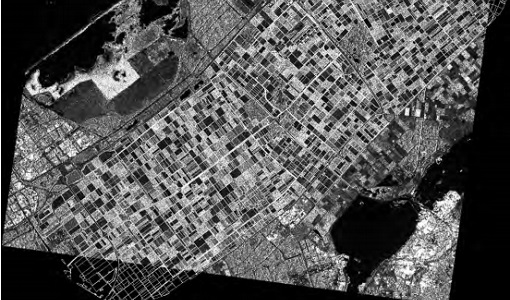
AgriSAR 2009
The AgriSAR 2009 campaign was defined to leverage the RADARSAT-2 mission to better understand and demonstrate the potential for GMES land monitoring user services, particularly in agriculture.
Data - Announcement of Opportunity (Restrained)

Closed ESA announcement of opportunities
Find out about closed ESA announcement of opportunities and what these opportunities involved, for historical reference.