- All Categories (214)
- Data (43)
- News (85)
- Missions (9)
- Events (29)
- Tools (7)
- Activities (4)
- Campaigns (24)
- Documents (13)
DATA
Discover and download the Earth observation data you need from the broad catalogue of missions the European Space Agency operate and support.
Data - EO Sign In Authentication (Open)
Sea Ice Thematic Data Product [ALT_TDP_SI]
This is the Sea Ice Thematic Data Product (TDP) V1 resulting from the ESA FDR4ALT project and containing the sea ice related geophysical parameters, along with associated uncertainties: snow depth, radar and sea-ice freeboard, sea ice thickness and concentration. The collection covers data for the ERS-1, ERS-2 and Envisat missions, and bases on Level 1 data coming from previous reprocessing (ERS REAPER and the Envisat V3.0) but taking into account the improvements made at Level 0/Level 1 in the frame of FDR4ALT (ALT FDR). The Sea Ice TDP provides data from the northern or southern hemisphere in two files corresponding to the Arctic and Antarctic regions respectively for the winter periods only, i.e., October to June for the Arctic, and May to November for the Antarctic. For many aspects, the Sea Ice TDP is very innovative: First time series of sea-ice thickness estimates for ERS Homogeneous calibration, allowing the first Arctic radar freeboard time series from ERS-1 (1991) to CryoSat-2 (2021) Uncertainties estimated along-track with a bottom-up approach based on dominant sources ERS pulse blurring error corrected using literature procedure [Peacock, 2004] The FDR4ALT products are available in NetCDF format. Free standard tools for reading NetCDF data can be used. Information for expert altimetry users is also available in a dedicated NetCDF group within the products. Please consult the FDR4ALT Product User Guide before using the data. The FDR4ALT datasets represent the new reference data for the ERS/Envisat altimetry missions, superseding any previous mission data. Users are strongly encouraged to make use of these datasets for optimal results.
Data - Sample Data (Open)

CryoSat Data Samples
Download CryoSat data samples from Baseline-B, C, and D products.
Data - EO Sign In Authentication (Open)
MOS-1/1B ESA Orthorectified Map-oriented Products [MES_GEC_1P]
The ESA Orthorectified Map-oriented (Level 1) Products collection is composed of MOS-1/1B MESSR (Multi-spectral Electronic Self-Scanning Radiometer) data products generated as part of the MOS Bulk Processing Campaign using the MOS Processor v3.02. The products are available in GeoTIFF format and disseminated within EO-SIP packaging. Please refer to the MOS Product Format Specification for further details. The collection consists of data products of the following type: MES_GEC_1P: Geocoded Ellipsoid GCP Corrected Level 1 MOS-1/1B MESSR products which are the default products generated by the MOS MESSR processor in all cases (where possible), with usage of the latest set of Landsat improved GCP (Ground Control Points). These are orthorectified map-oriented products, corresponding to the old MOS-1/1B MES_ORT_1P products with geolocation improvements. MESSR Instrument Characteristics Band Wavelength Range (nm) Spatial Resolution (m) Swath Width (km) 1 (VIS) 510 – 690 50 100 2 (VIS) 610 – 690 50 100 3 (NIR) 720 – 800 50 100 4 (NIR) 800 – 1100 50 100
Data - EO Sign In Authentication (Open)
MOS-1/1B ESA System Corrected Map-oriented Products [MES_GES_1P]
The ESA System Corrected Map-oriented (Level 1) Products collection is composed of MOS-1/1B MESSR (Multi-spectral Electronic Self-Scanning Radiometer) data products generated as part of the MOS Bulk Processing Campaign using the MOS Processor v3.02. The products are available in GeoTIFF format and disseminated within EO-SIP packaging. Please refer to the MOS Product Format Specification for further details. The collection consists of data products of the following type: MES_GES_1P: Geocoded Ellipsoid System Corrected Level 1 MOS-1/1B MESSR products as generated by the MOS MESSR processor where the generation of MES_GEC_1P products is not possible. These replace the old MES_SYC_1P products. MESSR Instrument Characteristics Band Wavelength Range (nm) Spatial Resolution (m) Swath Width (km) 1 (VIS) 510 – 690 50 100 2 (VIS) 610 – 690 50 100 3 (NIR) 720 – 800 50 100 4 (NIR) 800 – 1100 50 100
Data - EO Sign In Authentication (Open)
MOS-1/1B ESA System Corrected VTIR Products [VTI_SYC_1P]
The ESA System Corrected (Level 1) MOS-1/1B VTIR Products collection is composed of MOS-1/1B VTIR (Visible and Thermal Infrared Radiometer) data products generated as part of the MOS Bulk Processing Campaign using the MOS Processor v3.02. The products are available in GeoTIFF format and disseminated within EO-SIP packaging. Please refer to the MOS Product Format Specification for further details. The collection consists of data products of the following type: VTI_SYC_1P: System corrected Level 1 MOS-1/1B VTIR products in EO-SIP format. VTIR Instrument Characteristics Band Wavelength Range (µm) Spatial Resolution (km) Swath Width (km) 1 (VIS) 0.5 – 0.7 0.9 1500 2 (TIR) 6.0 – 7.0 2.7 1500 3 (TIR) 10.5 – 11.5 2.7 1500 4 (TIR) 11.5 – 12.5 2.7 1500
Data - EO Sign In Authentication (Open)
Aeolus L2A Aerosol/Cloud optical product
The Level 2A aerosol/cloud optical products of the Aeolus mission include: Geo-located consolidated backscatter and extinction profiles Backscatter-to-extinction coefficient LIDAR ratio, scene classification Heterogeneity index Attenuated backscatter signals. Resolution: Horizontal resolution of L2A optical properties at observation scale (~87 km); Exceptions are group properties (horizontal accumulation of measurements from ~3 km to ~87 km) and attenuated backscatters (~3 km). Note: The resolution of "groups" in the L2A can only go down to 5 measurements at the moment, i.e. ~15 km horizontal resolution. This could be configured to go to 1 measurement - Vertical resolution 250-2000 m (Defined by Range Bin Settings).
Data - Project Proposal (Restrained)
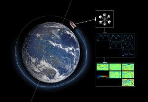
GHGSat archive and tasking
GHGSat data produce measures of vertical column densities of greenhouse gas emissions (typically CH4), provided on a pre-defined area of 12 km x 12 km, from the full sensor field-of-view. GHGSat Catalogue and New Collect data are available in three different data types: Single Observation: a single observation of a scene. Monthly Monitoring: guaranteed 12 successful observations in a year over a given site (once per month or flexible best effort cadence depending on weather). Weekly Monitoring: guaranteed 52 successful observations in a year over a given site (once a week or flexible best effort cadence based on weather), to accommodate large & persistent monitoring needs. Data are provided as an Emissions package containing the following products: Abundance dataset (Level 2): Set of per-pixel abundances (ppb or mol/m2) for a single species, and per-pixel measurement error expressed as a standard deviation for a single site on a single satellite pass. Data format is GeoTIFF (16-bit) or optionally GeoTIFF (32-bit or 64-bit floating point) Concentration Maps (Level 2): High readability pseudocolour map combining surface reflectance, and column density expressed in ppb or mol/m2 for a single species in PNG (optional PDF) format. The relevant abundance dataset is provided as well. Emission Rates (Level 4): Instantaneous emission rate from targeted source estimated using abundance datasets from a single satellite pass and applying dispersion modelling techniques in PDF format. The delivered product includes the emission rate estimate with uncertainty and key dispersion parameters (in CSV format) as well as the abundance dataset used for the emission estimate. The properties of available products are summarised in the table. Band(s) / Beam Mode(s) and Polarisation SWIR (1635-1675 nm), multiple bands, unpolarised Spatial Resolution <30 m Scene size 12 km x 12 km Species Measured CH4 Geometric Corrections Radial distortion, perspective projection Radiometric Corrections Detector pixel response, ghosting, spectral response, atmospheric correction including trace gas modelling and surface reflectance Details about the data provision, data access conditions and quota assignment procedure are described in the GHGSat Terms of Applicability.
Data - Project Proposal (Restrained)
SPOT-6 to 7 full archive and tasking
The SPOT 6 and 7 satellites ensure data continuity with the no longer operational SPOT 5 satellite and provide an archive of very high resolution optical acquisition as well as the possibility to task the satellites for new acquisitions. Following the completion of the SPOT 7 mission in March 2023, new acquisition tasking is only available for the SPOT 6 satellite. The ortho-products are automatically generated by the SPOT 6 and 7 ground segment, based on SRTM database or Reference3D when available. The projection available for SPOT 6 and 7 ortho-products is UTM, datum WGS84. Bands combinations: Pansharpened: colour image at 1.5 m resolution Bundle: 1.5 m panchromatic image and 6 m multispectral image. Geometric processing levels: Primary: The Primary product is the processing level closest to the natural image acquired by the sensor. This product restores perfect collection conditions: the sensor is placed in rectilinear geometry, and the image is clear of all radiometric distortion. Standard Ortho: The Ortho product is a georeferenced image in Earth geometry, corrected from acquisition and terrain off-nadir effects. Tailored ortho: Aside from the Standard Ortho product, when different specifications are needed, a custom orthorectification, with a more precise 3D model provided by the client or acquired for the purpose, can be provided on demand. As per ESA policy, very high-resolution imagery of conflict areas cannot be provided.
Data - Fast Registration with approval (Restrained)
RADARSAT-2 ESA archive
The RADARSAT-2 ESA archive collection consists of RADARSAT-2 products requested by ESA supported projects over their areas of interest around the world. The dataset regularly grows as ESA collects new products over the years. Following Beam modes are available: Standard, Wide Swath, Fine Resolution, Extended Low Incidence, Extended High Incidence, ScanSAR Narrow and ScanSAR Wide. Standard Beam Mode allows imaging over a wide range of incidence angles with a set of image quality characteristics which provides a balance between fine resolution and wide coverage, and between spatial and radiometric resolutions. Standard Beam Mode operates with any one of eight beams, referred to as S1 to S8, in single and dual polarisation . The nominal incidence angle range covered by the full set of beams is 20 degrees (at the inner edge of S1) to 52 degrees (at the outer edge of S8). Each individual beam covers a nominal ground swath of 100 km within the total standard beam accessibility swath of more than 500 km. Beam Mode Product Nominal Resolution (metres) Nominal Pixel Spacing Range x Azimuth (metres) Resolution Range x Azimuth (metres) Nominal Scene Size Range x Azimuth (kilometres) Range of Angle of Incidence (degrees) Number of Looks Range x Azimuth Polarisations Options Standard SLC 25 8.0 or 11.8 x 5.1 9.0 or 13.5 x 7.7 100 x 100 20 - 52 1 x 1 Single Pol HH or VV or HV or VH - or - Dual HH + HV or VV + VH SGX 8.0 x 8.0 26.8 - 17.3 x 24.7 1 x 4 SGF 12.5 x 12.5 SSG, SPG Wide Swath Beam Mode allows imaging of wider swaths than Standard Beam Mode, but at the expense of slightly coarser spatial resolution. The three Wide Swath beams, W1, W2 and W3, provide coverage of swaths of approximately 170 km, 150 km and 130 km in width respectively, and collectively span a total incidence angle range from 20 degrees to 45 degrees. Polarisation can be single and dual. Beam Mode Product Nominal Resolution (metres) Nominal Pixel Spacing Range x Azimuth (metres) Resolution Range x Azimuth (metres) Nominal Scene Size Range x Azimuth (kilometres) Range of Angle of Incidence (degrees) Number of Looks Range x Azimuth Polarisations Options Wide SLC 30 11.8 x 5.1 13.5 x 7.7 150 x 150 20 - 45 1 x 1 Single: Pol HH or VV or HV or VH - or - Dual: HH + HV or VV + VH SGX 10 x 10 40.0 - 19.2 x 24.7 1 x 4 SGF 12.5 x 12.5 SSG, SPG Fine Resolution Beam Mode is intended for applications which require finer spatial resolution. Products from this beam mode have a nominal ground swath of 50 km. Nine Fine Resolution physical beams, F23 to F21, and F1 to F6 are available to cover the incidence angle range from 30 to 50 degrees. For each of these beams, the swath can optionally be centred with respect to the physical beam or it can be shifted slightly to the near or far range side. Thanks to these additional swath positioning choices, overlaps of more than 50% are provided between adjacent swaths. RADARSAT-2 can operate in single and dual polarisation for this beam mode. Beam Mode Product Nominal resolution (metres) Nominal Pixel Spacing Range x Azimuth (metres) Resolution Range x Azimuth (metres) Nominal Scene Size Range x Azimuth (kilometres) Range of Angle of Incidence (degrees) Number of Looks Range x Azimuth Polarisations Options Fine SLC 8 4.7 x 5.1 5.2 x 7.7 50 x 50 30 - 50 1 x 1 Single: Pol HH or VV or HV or VH - or - Dual: HH + HV or VV + VH SGX 3.13 x 3.13 10.4 - 6.8 x 7.7 1 x 1 SGF 6.25 x 6.25 SSG, SPG In the Extended Low Incidence Beam Mode, a single Extended Low Incidence Beam, EL1, is provided for imaging in the incidence angle range from 10 to 23 degrees with a nominal ground swath coverage of 170 km. Some minor degradation of image quality can be expected due to operation of the antenna beyond its optimum scan angle range. Only single polarisation is available. Beam Mode Product Nominal resolution (metres) Nominal Pixel Spacing Range x Azimuth (metres) Resolution Range x Azimuth (metres) Nominal Scene Size Range x Azimuth (kilometres) Range of Angle of Incidence (degrees) Number of Looks Range x Azimuth Polarisations Options Extended Low SLC 25 8.0 x 5.1 9.0 x 7.7 170 x 170 10 - 23 1 x 1 Single: HH SGX 10.0 x 10.0 52.7 - 23.3 x 24.7 1 x 4 SGF 12.5 x 12.5 SSG, SPG In the Extended High Incidence Beam Mode, six Extended High Incidence Beams, EH1 to EH6, are available for imaging in the 49 to 60 degree incidence angle range. Since these beams operate outside the optimum scan angle range of the SAR antenna, some degradation of image quality, becoming progressively more severe with increasing incidence angle, can be expected when compared with the Standard Beams. Swath widths are restricted to a nominal 80 km for the inner three beams, and 70 km for the outer beams. Only single polarisation available. Beam Mode Product Nominal resolution (metres) Nominal Pixel Spacing Range x Azimuth (metres) Resolution Range x Azimuth (metres) Nominal Scene Size Range x Azimuth (kilometres) Range of Angle of Incidence (degrees) Number of Looks Range x Azimuth Polarisations Options Extended High SLC 25 11.8 x 5.1 13.5 x 7.7 75 x 75 49 - 60 1 x 1 Single Pol HH SGX 8.0 x 8.0 18.2 - 15.9 x 24.7 1 x 4 SGF 12.5 x 12.5 SSG, SPG ScanSAR Narrow Beam Mode provides coverage of a ground swath approximately double the width of the Wide Swath Beam Mode swaths. Two swath positions with different combinations of physical beams can be used: SCNA, which uses physical beams W1 and W2, and SCNB, which uses physical beams W2, S5, and S6. Both options provide coverage of swath widths of about 300 km. The SCNA combination provides coverage over the incidence angle range from 20 to 39 degrees. The SCNB combination provides coverage over the incidence angle range 31 to 47 degrees. RADARSAT-2 can operate in single and dual polarisation for this beam mode. Beam Mode Product Nominal resolution (metres) Nominal Pixel Spacing Range x Azimuth (metres) Resolution Range x Azimuth (metres) Nominal Scene Size Range x Azimuth (kilometres) Range of Angle of Incidence (degrees) Number of Looks Range x Azimuth Polarisations Options ScanSAR Narrow SCN, SCF, SCS 20 25 x 25 81 - 38 x 40 - 70 300 x 300 20 - 46 2 x 2 Single Co or Cross: HH or VV or HV or VH - or - Dual: HH + HV or VV + VH ScanSAR Wide Beam Mode provides coverage of a ground swath approximately triple the width of the Wide Swath Beam Mode swaths. Two swath positions with different combinations of physical beams can be used: SCWA, which uses physical beams W1, W2, W3, and S7, and SCWB, which uses physical beams W1, W2, S5 and S6. The SCWA combination allows imaging of a swath of more than 500 km covering an incidence angle range of 20 to 49 degrees. The SCWB combination allows imaging of a swath of more than 450 km covering the incidence angle. Polarisation can be single and dual. Beam Mode Product Nominal resolution (metres) Nominal Pixel Spacing Range x Azimuth (metres) Resolution Range x Azimuth (metres) Nominal Scene Size Range x Azimuth (kilometres) Range of Angle of Incidence (degrees) Number of Looks Range x Azimuth Polarisations Options ScanSAR Wide SCW, SCF, SCS 100 50 x 50 163 - 73 x 78 - 106 500 x 500 20 - 49 4 x 2 Single Co or Cross: HH or VV or HV or VH - or - Dual: HH + HV or VV + VH These are the different products : SLC (Single Look Complex): Amplitude and phase information is preserved. Data is in slant range. Georeferenced and aligned with the satellite track SGF (Path Image): Data is converted to ground range and may be multi-look processed. Scene is oriented in direction of orbit path. Georeferenced and aligned with the satellite track. SGX (Path Image Plus): Same as SGF except processed with refined pixel spacing as needed to fully encompass the image data bandwidths. Georeferenced and aligned with the satellite track SSG(Map Image): Image is geocorrected to a map projection. SPG (Precision Map Image): Image is geocorrected to a map projection. Ground control points (GCP) are used to improve positional accuracy. SCN(ScanSAR Narrow)/SCF(ScanSAR Wide) : ScanSAR Narrow/Wide beam mode product with original processing options and metadata fields (for backwards compatibility only). Georeferenced and aligned with the satellite track SCF (ScanSAR Fine): ScanSAR product equivalent to SGF with additional processing options and metadata fields. Georeferenced and aligned with the satellite track SCS(ScanSAR Sampled) : Same as SCF except with finer sampling. Georeferenced and aligned with the satellite track. Spatial coverage: Check the spatial coverage of the collection on a map available on the Third Party Missions Dissemination Service.
Data - Announcement of Opportunity (Restrained)
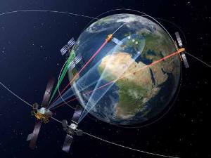
Announcement of Opportunity for NoR
ESA invites submissions for the Network of Resources (NoR) call, which aims to support research, development and pre-commercial users to innovate their working practices, moving from a data download paradigm towards a 'bring the user to the data' paradigm.
Data - EO Sign In Authentication (Open)
SMOS - CryoSat L4 Sea Ice Thickness
The SMOS-CryoSat merged Sea Ice Thickness Level 4 product, in NetCDF format, is based on estimates from both the MIRAS and the SIRAL instruments with a significant reduction in the relative uncertainty for the thickness of the thin ice. A weekly averaged preliminary product is generated every day by the Alfred Wegener Institut (AWI) by merging the weekly CryoSat Sea Ice Thickness product and the daily SMOS Sea Ice Thickness retrieval. A final product is provided with a latency of about 3-4 weeks using a different global sea ice concentration product and a reprocessed CryoSat product. All grids are projected onto the 25 km EASE2 Grid based on a polar aspect spherical Lambert azimuthal equal-area projection. The grid dimension is 5400 x 5400 km, equal to a 432 x 432 grid centered on the geographic pole. Coverage is limited to the October-April (winter) period for the Northern Hemisphere, due to the melting season, from year 2010 onwards.
Data - Fast Registration with approval (Restrained)

SPOT 6 and 7 ESA archive
The SPOT 6 and 7 ESA archive is a dataset of SPOT 6 and SPOT 7 products that ESA collected over the years. The dataset regularly grows as ESA collects new SPOT 6 and 7 products. SPOT 6 and 7 Primary and Ortho products can be available in the following modes: Panchromatic image at 1.5m resolution Pansharpened colour image at 1.5m resolution Multispectral image in 4 spectral bands at 6m resolution Bundle (1.5m panchromatic image + 6m multispectral image) Spatial coverage: Check the spatial coverage of the collection on a map available on the Third Party Missions Dissemination Service. As per ESA policy, very high-resolution imagery of conflict areas cannot be provided.
Data - Fast Registration with approval (Restrained)

SPOT 1-5 ESA archive
The ESA SPOT 1-5 collection is a dataset of SPOT 1 to 5 Panchromatic and Multispectral products that ESA collected over the years. The HRV(IR) sensor onboard SPOT 1-4 provides data at 10 m spatial resolution Panchromatic mode (-1 band) and 20 m (Multispectral mode -3 or 4 bands). The HRG sensor on board of SPOT-5 provides spatial resolution of the imagery to < 3 m in the panchromatic band and to 10 m in the multispectral mode (3 bands). The SWIR band imagery remains at 20 m. The dataset mainly focuses on European and African sites but some American, Asian and Greenland areas are also covered. Spatial coverage: Check the spatial coverage of the collection on a map available on the Third Party Missions Dissemination Service. The SPOT Collection
Data - External Data (Restrained)
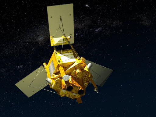
SciSat-1: ACE-FTS and MAESTRO
SCISAT-1 data aim at monitoring and analysing the chemical processes that control the distribution of ozone in the upper troposphere and stratosphere. It provides acquisitions from the two instruments MAESTRO and ACE-FTS. MAESTRO: Measurement of Aerosol Extinction in the Stratosphere and Troposphere Retrieved by Occultation. Dual-channel optical spectrometer in the spectral region of 285-1030 nm. The objective is to measure ozone, nitrogen dioxide and aerosol/cloud extinction (solar occultation measurements of atmospheric attenuation during satellite sunrise and sunset with the primary objective of assessing the stratospheric ozone budget). Solar occultation spectra are being used for retrieving vertical profiles of temperature and pressure, aerosols, and trace gases (O3, NO2, H2O, OClO, and BrO) involved in middle atmosphere ozone distribution. The use of two overlapping spectrometers (280 - 550 nm, 500 - 1030 nm) improves the stray-light performance. The spectral resolution is about 1-2 nm. ACE-FTS: Fourier Transform Spectrometer. The objective is to measure the vertical distribution of atmospheric trace gases, in particular of the regional polar O3 budget, as well as pressure and temperature (derived from CO2 lines). The instrument is an adapted version of the classical sweeping Michelson interferometer, using an optimised optical layout. The ACE-FTS measurements are recorded every 2 s. This corresponds to a measurement spacing of 2-6 km which decreases at lower altitudes due to refraction. The typical altitude spacing changes with the orbital beta angle. For historical reasons, the retrieved results are interpolated onto a 1 km "grid" using a piecewise quadratic method. For ACE-FTS version 1.0, the results were reported only on the interpolated grid (every 1 km from 0.5 to 149.5 km). For versions 2.2, both the "retrieval" grid and the "1 km" grid profiles are available. SCISAT-1 collection provides ACE-FTS and MAESTRO Level 2 Data. As of today, ACE-FTS products are available in version 4.1, while MAESTRO products are available in version 3.13.
Data - Data Description
ERS-1/2 Radar Altimeter REAPER METEO Product - [ERS_ALT_2M]
This is a RA Meteo product containing only the 1 Hz parameters for altimeter (surface range, satellite altitude, wind speed and significant wave height at nadir) and ATSR/MWR data (brightness temperature at 23.8 GHz and 36.5 GHz, water vapour content, liquid water content) used to correct altimeter measurements. It also contains the full geophysical corrections. This product corresponds to a subset of the REAPER GDR product (ERS_ALT_2_). The REAPER (REprocessing of Altimeter Products for ERS) product is generated by applying a similar processing as for Envisat RA-2 on the Level 1b consolidated waveforms using 4 different re-trackers, RA calibration improvement, new precise orbit solution (POD), new ionospheric corrections (NICO09 until 1998 and GIM up to 2003), ECMWF ERA-interim model and updated SSB tables. This product contains only the low rate of 1 Hz data. The REAPER Meteo (ERS_ALT_2M) is a global product including data over ocean, ice and land. It should be noted that this product differs from the Envisat RA2 in the following ways: The product format; which is NetCDF (more details can be found in the Product Handbook), and not PDS The product is delivered based on orbit acquisition and not per pass (pole-to-pole). This product is extended through Envisat RA-2 data.
Data - Fast Registration with immediate access (Open)
Envisat RA-2 Sensor and Geophysical Data Record - SGDR [RA2_MWS__2P]
This is a RA-2 Sensor and Geophysical Data Record (SGDR) Full Mission Reprocessing (FMR) V3 product. This FMR follows the first Envisat Altimetry reprocessing Version (V2.1) completed in 2012. The GDR and S-GDR data products were reprocessed for all cycles from 6 to 113 (May 2002 to April 2012) into a homogeneous standard in NetCDF format (close to Sentinel-3). The Sensor Data Record (SGDR) Product from RA-2/MWR includes the data in the GDR product (RA-2 geophysical data, MWR data) and also RA-2 averaged waveforms (18Hz) and RA-2 individual waveforms (1800Hz). This product is a continuation of ERS RA data. This data product has a coverage of 1 pass and pole to pole, a spatial sampling of about 390 m along track and a size of 31 to 40 MB, depending on presence of individual waveforms. The radiometric accuracy is 0.2 dB and auxiliary data include: Orbit state vectors (DORIS, FOS), RA2 and MWR characterisation data, Platform attitude, Gain calibration, USO frequency, ECMWF data, time relation, leap second, Ionospheric corrections, geoid, mean sea surface, slope data, and tide model (ocean, earth, loading, pole). Please consult the Envisat RA-2/MWR Product Quality Readme file before using the data.
Data - Fast Registration with immediate access (Open)
Envisat RA-2 Geophysical Data Record - GDR [RA2_GDR__2P]
This is a RA-2 Geophysical Data Record (GDR) Full Mission Reprocessing (FMR) V3 product containing radar range and orbital altitude, wind speed, wave height, water vapour from the MWR and geophysical corrections. This FMR follows the first Envisat Altimetry reprocessing Version (V2.1) completed in 2012. The GDR and S-GDR data products were reprocessed for all cycles from 6 to 113 (May 2002 to April 2012) into a homogeneous standard in NetCDF format (close to Sentinel-3). For many aspects, the V3.0 reprocessed data are better than the previous dataset: In terms of available and valid data, the coverage is better, notably thanks to a better availability of MWR data at the beginning of the mission In terms of performance at cross-overs, the quality is improved: the annual signal and average of Mean SSH is decreased, as well as the standard deviation The new MWR characteristics were shown to improve largely the global quality of data. As well as the new tide model, the new MSS and the new orbit standard The Global and regional Mean Sea Level trend is very weakly impacted though the effort was put, this time, on the mesoscale restitution, rather than long term drift, as during V2.1 reprocessing. Please consult the Envisat RA-2/MWR Product Quality Readme file PDF before using the data.
Data - Project Proposal (Restrained)
Pléiades full archive and tasking
The Pléiades twins (1A and 1B) deliver very high-resolution optical data (up to 0.5 m resolution Panchromatic and Colour and 2 m Multispectral) and offer a daily revisit capability to any point on the globe. The swath width is approximately 20 km (with a nadir footprint). The ortho-products are automatically generated by the Pléiades ground segment, based on SRTM or Reference3D database. The projection available for Pléiades ortho-products is UTM, datum WGS84. Bands combinations:: Pansharpened: colour image at 0.5 m resolution Bundle: (0.5 m panchromatic image + 2 m multispectral image) Processing levels: Primary: The Primary product is the processing level closest to the natural image acquired by the sensor. This product restores perfect collection conditions: the sensor is placed in rectilinear geometry, and the image is clear of all radiometric distortion. Standard Ortho: The Ortho product is a georeferenced image in Earth geometry, corrected from acquisition and terrain off-nadir effects. Tailored Ortho: Aside from the Standard Ortho product, when different specifications are needed, a custom orthorectification, with a more precise 3D model provided by the client or acquired for the purpose, can be provided on demand. As per ESA policy, very high-resolution imagery of conflict areas cannot be provided.
Data - EO Sign In Authentication (Open)
SMOS L3 Sea Ice Thickness
The SMOS Level 3 Sea Ice Thickness product, in NetCDF format, provides daily estimations of SMOS-retrieved sea ice thickness (and its uncertainty) at the edge of the Arctic Ocean during the October-April (winter) season, from year 2010 onwards. The sea ice thickness is retrieved from the SMOS L1C product, up to a depth of approximately 0.5-1 m, depending on the ice temperature and salinity. Daily maps, projected on polar stereographic grid of 12.5 km, are generated by the Alfred Wegener Institut (AWI). This product is complementary with sea ice thickness measurements from ESA's CryoSat and Copernicus Sentinel-3 missions.
Data - Project Proposal (Restrained)
RADARSAT-1 & 2 full archive and tasking
RADARSAT-1 products The Standard beam mode operates with any one of seven beam positions, referred to as S1 to S7. The nominal incidence angle range covered by the full set of Standard beams is from 20 degrees (at the inner edge of S1) to 49 degrees (at the outer edge of S7). Each individual beam covers a minimum ground swath of 100 km within the total 500 km accessibility swath of the full set of Standard beams. The nominal spatial resolution in the range direction is 26 m for S1 at near range to 20 m for S7 at far range. The nominal azimuth resolution is the same, 27 m, for all beam positions. The Wide beam modes are similar to the Standard beams except that the swath width achieved by this beam is 150 km rather than 100 km. As a result, only three Wide beams, W1, W2 and W3 are necessary to provide coverage of almost all of the 500 km swath range. They provide comparable resolution to the standard beam mode, though the increased ground swath coverage is obtained at the expense of a slight reduction in overall image quality. In the Fine beam mode the nominal azimuth resolution is 8.4 m, with range resolution 9.1 m to 7.8 m from F1 to F5. Since the radar operates with a higher sampling rate in this mode than in any of the other beam mode, the ground swath coverage has to be reduced to approximately 50 km in order to keep the downlink signal within its allocated bandwidth. Originally, five Fine beam positions, F1 to F5, were available to cover the far range of the swath with an incidence angle range from 37 to 47 degrees. By modifying timing parameters, 10 new positions have been added with offset ground coverage. Each original Fine beam position can either be shifted closer to or further away from Nadir. In Extended High beam mode six positions, EH1 to EH6, are available for collection of data in the 49 to 60 degree incidence angle range. Since this beam mode operates outside the optimum scan angle range of the SAR antenna, some minor degradation of image quality can be expected when compared with the Standard beam mode. Swath widths are restricted to a nominal 80 km for the inner three positions, and 70 km for the outer three positions. In Extended Low beam mode one position, EL1, is provided for imaging in the incidence angle range 10 to 23 degrees with nominal ground swath coverage of 170 km. As with the Extended High beam mode, some minor degradation of image quality can be expected due to operation of the antenna beyond its optimum elevation angle range. In ScanSAR mode, combinations of two, three or four single beams are used during data collection. Each beam is selected sequentially so that data is collected from a wider swath than possible with a single beam. The beam switching rates are chosen to ensure at least one "look" at the Earth's surface for each beam within the along track illumination time or dwell time of the antenna beam. In practice, the radar beam switching is adjusted to provide two looks per beam. The beam multiplexing inherent in ScanSAR operation reduces the effective sampling rate within each of the component beams; hence the increased swath coverage is obtained at the expense of spatial resolution. The ScanSAR Narrow mode combines two beams (incidence angle range of 20 to 39 degrees) or three beams (incidence angle from 31 to 46 degrees) and provides coverage of a nominal 300 km ground swath, with spatial resolution of 50 m. The ScanSAR Wide mode combines four beams, provides coverage of either 500 km (with incidence angle range of 20 to 49 degrees) or 450 km (incidence angle range from 20 to 46 degrees) nominal ground swaths depending on the beam combination. Beam Mode Product Ground coverage (km2) Nominal resolution (m) Polarisation ScanSAR wide SCW, SCF, SCS 500 x 500 100 Single and dual ScanSAR narrow SCN, SCF, SCS 300 x 300 60 Single and dual Wide SGF, SGX, SLC, SSG, SPG 150 x 150 24 Single and dual Standard SGF, SGX, SLC, SSG, SPG 100 x 100 24 Single Extended low SGF, SGX, SLC, SSG, SPG 170 x 170 24 Single Extended high SGF, SGX, SLC, SSG, SPG 75 x 75 24 Single Fine SGF, SGX, SLC, SSG, SPG 50 x 50 8 Single RADARSAT-2 products The Standard Beam Mode allows imaging over a wide range of incidence angles with a set of image quality characteristics which provides a balance between fine resolution and wide coverage, and between spatial and radiometric resolutions. Standard Beam Mode operates with any one of eight beams, referred to as S1 to S8. The nominal incidence angle range covered by the full set of beams is 20 degrees (at the inner edge of S1) to 52 degrees (at the outer edge of S8). Each individual beam covers a nominal ground swath of 100 km within the total standard beam accessibility swath of more than 500 km. The Wide Swath Beam Mode allows imaging of wider swaths than Standard Beam Mode, but at the expense of slightly coarser spatial resolution. The three Wide Swath beams, W1, W2 and W3, provide coverage of swaths of approximately 170 km, 150 km and 130 km in width respectively, and collectively span a total incidence angle range from 20 degrees to 45 degrees. The Fine Resolution Beam Mode is intended for applications which require finer spatial resolution. Products from this beam mode have a nominal ground swath of 50 km. Nine Fine Resolution physical beams, F23 to F21, and F1 to F6 are available to cover the incidence angle range from 30 to 50 degrees. For each of these beams, the swath can optionally be centred with respect to the physical beam or it can be shifted slightly to the near or far range side. Thanks to these additional swath positioning choices, overlaps of more than 50% are provided between adjacent swaths. In the Extended Low Incidence Beam Mode, a single Extended Low Incidence Beam, EL1, is provided for imaging in the incidence angle range from 10 to 23 degrees with a nominal ground swath coverage of 170 km. Some minor degradation of image quality can be expected due to operation of the antenna beyond its optimum scan angle range. In the Extended High Incidence Beam Mode, six Extended High Incidence Beams, EH1 to EH6, are available for imaging in the 49 to 60 degree incidence angle range. Since these beams operate outside the optimum scan angle range of the SAR antenna, some degradation of image quality, becoming progressively more severe with increasing incidence angle, can be expected when compared with the Standard Beams. Swath widths are restricted to a nominal 80 km for the inner three beams, and 70 km for the outer beams. ScanSAR Narrow Beam Mode provides coverage of a ground swath approximately double the width of the Wide Swath Beam Mode swaths. Two swath positions with different combinations of physical beams can be used: SCNA, which uses physical beams W1 and W2, and SCNB, which uses physical beams W2, S5, and S6. Both options provide coverage of swath widths of about 300 km. The SCNA combination provides coverage over the incidence angle range from 20 to 39 degrees. The SCNB combination provides coverage over the incidence angle range 31 to 47 degrees. ScanSAR Wide Beam Mode provides coverage of a ground swath approximately triple the width of the Wide Swath Beam Mode swaths. Two swath positions with different combinations of physical beams can be used: SCWA, which uses physical beams W1, W2, W3, and S7, and SCWB, which uses physical beams W1, W2, S5 and S6. The SCWA combination allows imaging of a swath of more than 500 km covering an incidence angle range of 20 to 49 degrees. The SCWB combination allows imaging of a swath of more than 450 km covering the incidence angle. In the Standard Quad Polarization Beam Mode, the radar transmits pulses alternately in horizontal (H) and vertical (V) polarisations, and receives the return signals from each pulse in both H and V polarisations separately but simultaneously. This beam mode therefore enables full polarimetric (HH+VV+HV+VH) image products to be generated. The Standard Quad Polarization Beam Mode operates with the same pulse bandwidths as the Standard Beam Mode. Products with swath widths of approximately 25 km can be obtained covering any area within the region from an incidence angle of 18 degrees to at least 49 degrees. The Wide Standard Quad Polarization Beam Mode operates the same way as the Standard Quad Polarization Beam Mode but with higher data acquisition rates, and offers wider swaths of approximately 50 km at equivalent spatial resolution. 21 beams are available covering any area from 18 degrees to 42 degrees, ensuring overlaps of about 50% between adjacent swaths. The Fine Quad Polarization Beam Mode provides full polarimetric imaging with the same spatial resolution as the Fine Resolution Beam Mode. Fine Quad Polarization Beam Mode products with swath widths of approximately 25 km can be obtained covering any area within the region from an incidence angle of 18 degrees to at least 49 degrees. The Wide Fine Quad Polarization Beam Mode operates the same way as the Fine Quad Polarization Beam Mode but with higher data acquisition rates, and offers a wider swath of approximately 50 km at equivalent spatial resolution. 21 beams are available covering any area from 18 degrees to 42 degrees, ensuring overlaps of about 50% between adjacent swaths. The Multi-Look Fine Resolution Beam Mode covers the same swaths as the Fine Resolution Beam Mode. Products with multiple looks in range and azimuth are generated at approximately the same spatial resolution as Fine Resolution Beam mode products, but with multiple looks and therefore improved radiometric resolution. Single look products are generated at finer spatial resolutions than Fine Resolution Beam Mode products. In order to obtain the multiple looks without a reduction in swath width, this beam mode operates with higher data acquisition rates and noise levels than Fine Resolution Beam Mode. As with the Fine Resolution Beam Mode, nine physical beams are available to cover the incidence angle range from 30 to 50 degrees, and additional near and/or far range swath positioning choices are available to provide additional overlap. The Wide Multi-Look Fine Resolution Beam Mode offers a wider coverage alternative to the regular Multi-Look Fine Beam Mode, while preserving the same spatial and radiometric resolution, but at the expense of higher data compression ratios (which leads to higher signal-dependent noise levels). The nominal swath width is 90 km compared to 50 km for the Multi-Look Fine Beam Mode. The nine physical beams are the same as in the Multi-Look Fine Beam Mode, covering incidence angles from approximately 30 to 50 degrees, but the additional near and far range swath positioning choices available in the Multi-Look Fine Beam Mode are not needed because the beam centered swaths are wide enough to overlap by more than 50%. The Ultra-Fine Resolution Beam Mode is intended for applications which require very high spatial resolution. The set of Ultra-Fine Resolution Beams cover any area within the incidence angle range from 20 to 50 degrees (soon to be extended to 54 degrees). Each beam within the set images a swath width of at least 20 km. The Wide Ultra-Fine Resolution Beam Mode provides the same spatial resolution as the Ultra-Fine mode as well as wider coverage, but at the expense of higher data compression ratios (which leads to higher signal-dependent noise levels). The set of Wide Ultra-Fine Resolution Beams cover any area within the incidence angle range from 30 to 50 degrees. Each beam within the set images a swath width of approximately 50 km. The Wide Fine Resolution Beam Mode is intended for applications which require both a finer spatial resolution and a wide swath. Products from this beam mode have a nominal ground swath equivalent to the ones offered by the Wide Swath Beam Mode (170 km, 150 km and 120 km) and a spatial resolution equivalent to the ones offered by the Fine Resolution Beam Mode, at the expense of somewhat higher noise levels. Three Wide Fine Resolution beam positions, F0W1 to F0W3 are available to cover the incidence angle range from 20 to 45 degrees. The Extra-Fine Resolution Beam Mode nominally provides similar swath width and incidence angle coverage as the Wide Fine Beam Mode, at even finer resolutions, but with higher data compression ratios and noise levels. The four Extra-Fine beams provide coverage of swaths of approximately 160 km, 124 km, 120 km and 108 km in width respectively, and collectively span a total incidence angle range from 22 to 49 degrees. This beam mode also offers additional optional processing parameter selections that allow for reduced-bandwidth single-look products, 4-look, and 28-look products. In Spotlight Beam Mode, the beam is steered electronically in order to dwell on the area of interest over longer aperture times, which allows products to be processed to finer azimuth resolution than in other modes. Unlike in other modes, Spotlight images are of fixed size in the along track direction. The set of Spotlight beams cover any area within the incidence angle range from 20 to 50 degrees (soon to be extended to 54 degrees). Each beam within the set images a swath width of at least 18 km. Beam Mode Product Nominal Pixel Spacing [Range x Azimuth] (metres) Nominal Resolution (metres) Resolution [Range x Azimuth] (metres) Nominal Scene Size [Range x Azimuth] (kilometres) Range of Angle of Incidence [Range] (degrees) Number of Looks [Range x Azimuth] Polarisations Options Spotlight SLC 1.3 x 0.4 <1 1.6 x 0.8 18 x 8 20 to 54 1 x 1 Single Co or Cross (HH or VV or HV or VH) SGX 1 or 0.8 x 1/3 4.6 - 2.0 x 0.8 SGF 0.5 x 0.5 SSG, SPG Ultra-fine SLC 1.3 x 2.1 3 1.6 x 2.8 20 x 20 20 to 54 1 x 1 Single Co or Cross (HH or VV or HV or VH) SGX 1 x 1 or 0.8 x 0.8 3.3 – 2.1 x 2.8 SGF 1.56 x 1.56 SSG, SPG Wide Ultra-fine SLC 1.3 x 2.1 3 3.1 x 4.6 50 x 50 29 to 50 1 x 1 Single Co or Cross (HH or VV or HV or VH) SGX 1 x 1 3.3 - 2.1 x 2.8 SGF 1.56 x 1.56 SSG, SPG Multi-look fine SLC 2.7 x 2.9 8 3.1 x 4.6 50 x 50 30 to 50 1 x 1 Single Co or Cross (HH or VV or HV or VH) SGX 3.13 x 3.13 10.4 - 6.8 x 7.6 2 x 2 SGF 6.25 x 6.25 SSG, SPG Wide Multi-look fine SLC 2.7 x 2.9 8 3.1 x 4.6 90 x 50 29 to 50 1 x 1 Single Co or Cross (HH or VV or HV or VH) SGX 3.13 x 3.13 10.8 - 6.8 x 7.6 2 x 2 SGF 6.25 x 6.25 SSG, SPG Extra-fine SLC (Full resolution) 2.7 x 2.9 5 3.1 x 4.6 125 x 125 22 to 49 1 x 1 Single Co or Cross (HH or VV or HV or VH) SLC (fine resolution) 4.3 x 5.8 5.2 x 7.6 SLC (standard resolution) 7.1 x 5.8 8.9 x 7.6 SLC (wide resolution) 10.6 x 5.8 13.3 x 7.6 SGX (1 look) 2.0 x 2.0 8.4 – 4.1 x 4.6 SGX (4 looks) 3.13 x 3.13 14 – 6.9 x 7.6 2 x 2 SGX (28 looks) 5.0 x 5.0 24 - 12 x 23.5 4 x 7 SGF (1 look) 3.13 x 3.13 8.4 - 4.1 x 4.6 1 x 1 SGF (4 looks) 6.25 x 6.25 14 - 6.9 x 7.6 2 x 2 SGF (28 looks) 8.0 x 8.0 24 - 12 x 23.5 4 x 7 SSG, SPG 3.13 x 3.13 8.4 - 4.1 x 4.6 1 x 1 Fine SLC 4.7 x 5.1 8 5.2 x 7.7 50 x 50 30 to 50 1 x 1 Single Co or Cross (HH or VV or HV or VH) or Dual (HH+HV or VV+VH) SGX 3.13 x 3.13 10.4 – 6.8 x 7.7 SGF 6.25 x 6.25 SSG, SPG Wide Fine SLC 4.7 x 5.1 8 5.2 x 7.7 150 x 150 20 to 45 1 x 1 Single Co or Cross (HH or VV or HV or VH) or Dual (HH+HV or VV+VH) SGX 3.13 x 3.13 14.9 - 7.3 x 7.7 SGF 6.25 x 6.25 SSG, SPG Standard SLC 8.0 or 11.8 x 5.1 25 9.0 or 13.5 x 7.7 100 x 100 20 - 52 1 x 1 Single Co or Cross (HH or VV or HV or VH) or Dual (HH+HV or VV+VH) SGX 8 x 8 26.8 - 17.3 x 24.7 1 x 4 SGF 12.5 x 12.5 SSG, SPG Wide SLC 11.8 x 5.1 30 13.5 x 7.7 150 x 150 20 - 45 1 x 1 Single Co or Cross (HH or VV or HV or VH) or Dual (HH+HV or VV+VH) SGX 10 x 10 40.0 - 19.2 x 24.7 1 x 4 SGF 12.5 x 12.5 SSG, SPG Extended High SLC 11.8 x 5.1 25 13.5 x 7.7 75 x 75 49 - 60 1 x 1 Single (HH only) SGX 8 x 8 18.2 - 15.9 x 24.7 1 x 4 SGF 12.5 x 12.5 SSG, SPG Extended Low SLC 8.0 x 5.1 25 9.0 x 7.7 170 x 170 10 - 23 1 x 1 Single (HH only) SGX 10 x 10 52.7 – 23.3 x 24.7 1 x 4 SGF 12.5 x 12.5 SSG, SPG Fine Quad-Pol SLC 4.7 x 5.1 8 5.2 x 7.6 25 x 25 18 - 49 1 x 1 Quad (HH+VV+HV+VH) SGX 3.13 x 3.13 16.5 – 6.8 x 7.6 1 x 1 SSG, SPG Wide Fine Quad-Pol SLC 4.7 x 5.1 8 5.2 x 7.6 50 x 25 18 - 42 1 x 1 Quad (HH+VV+HV+VH) SGX 3.13 x 3.13 17.3–7.8 x 7.6 SSG, SPG Standard Quad-Pol SLC 8 or 11.8 x 5.1 25 9.0 or 13.5 x 7.6 25 x 25 18 - 49 1 x 1 Quad (HH+VV+HV+VH) SGX 8 x 3.13 28.6 – 17.7 x 7.6 SSG, SPG Wide Standard Quad-Pol SLC 8 or 11.8 x 5.1 25 9.0 or 13.5 x 7.6 50 x 25 18 - 42 1 x 1 Quad (HH+VV+HV+VH) SGX 8 x 3.13 30.0 –16.7 x 7.6 SSG, SPG ScanSAR Narrow SCN, SCF, SCS 25 x 25 50 81–38 x 40-70 300 x 300 20 to 46 2 x 2 Single Co or Cross (HH or VV or HV or VH) or Dual (HH+HV or VV+VH) ScanSAR Wide SCW, SCF, SCS 50 x 50 100 163-73 x 78-106 500 x 500 20 to 49 4 x 2 Single Co or Cross (HH or VV or HV or VH) or Dual (HH+HV or VV+VH) These are the different products : SLC (Single Look Complex): Amplitude and phase information is preserved. Data is in slant range. Georeferenced and aligned with the satellite track SGF (Path Image): Data is converted to ground range and may be multi-look processed. Scene is oriented in direction of orbit path. Georeferenced and aligned with the satellite track. SGX (Path Image Plus): Same as SGF except processed with refined pixel spacing as needed to fully encompass the image data bandwidths. Georeferenced and aligned with the satellite track SSG (Map Image): Image is geocorrected to a map projection. SPG (Precision Map Image): Image is geocorrected to a map projection. Ground control points (GCP) are used to improve positional accuracy. SCN (ScanSAR Narrow)/SCF(ScanSAR Wide) : ScanSAR Narrow/Wide beam mode product with original processing options and metadata fields (for backwards compatibility only). Georeferenced and aligned with the satellite track SCF (ScanSAR Fine): ScanSAR product equivalent to SGF with additional processing options and metadata fields. Georeferenced and aligned with the satellite track SCS (ScanSAR Sampled) : Same as SCF except with finer sampling. Georeferenced and aligned with the satellite track.