- All Categories (41441)
- Data (103)
- News (167)
- Missions (25)
- Events (63)
- Tools (7)
- Activities (10)
- Campaigns (22)
- Documents (41044)
DATA
Discover and download the Earth observation data you need from the broad catalogue of missions the European Space Agency operate and support.
Data - Project Proposal (Restrained)
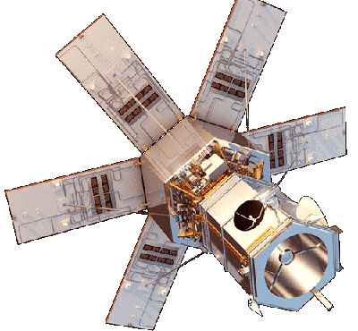
WorldView-4 Full Archive
WorldView-4 high resolution optical products are available as part of the Maxar Standard Satellite Imagery products from the QuickBird, WorldView-1/-2/-3/4, and GeoEye-1 satellites. All details about the data provision, data access conditions and quota assignment procedure are described into the Terms of Applicability available in Resources section. In particular, WorldView-4 offers archive panchromatic products up to 0.31 m GSD resolution, and 4-Bands Multispectral products up to 1.24 m GSD resolution. Band Combination Data Processing Level Resolution Panchromatic and 4-bands Standard (2A) / View Ready Standard (OR2A) 15 cm HD, 30 cm HD, 30 cm, 40 cm, 50/60 cm View Ready stereo 30 cm, 40 cm, 50/60 cm Map Ready (Ortho) 1:12.000 Orthorectified 15 cm HD, 30 cm HD, 30 cm, 40 cm, 50/60 cm The options for 4-Bands are the following: 4-Band Multispectral (BLUE, GREEN, RED, NIR1) 4-Band Pan-sharpened (BLUE, GREEN, RED, NIR1) 4-Band Bundle (PAN, BLUE, GREEN, RED, NIR1) 3-Bands Natural Colour (pan-sharpened BLUE, GREEN, RED) 3-Band Colored Infrared (pan-sharpened GREEN, RED, NIR1) Native 30 cm and 50/60 cm resolution products are processed with MAXAR HD Technology to generate respectively the 15 cm HD and 30 cm HD products: the initial special resolution (GSD) is unchanged but the HD technique increases the number of pixels and improves the visual clarity achieving aesthetically refined imagery with precise edges and well-reconstructed details.
Data - Project Proposal (Restrained)
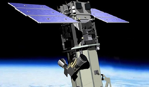
WorldView-3 full archive and tasking
WorldView-3 high resolution optical products are available as part of the Maxar Standard Satellite Imagery products from the QuickBird, WorldView-1/-2/-3/-4, and GeoEye-1 satellites. All details about the data provision, data access conditions and quota assignment procedure are described into the Terms of Applicability available in Resources section. In particular, WorldView-3 offers archive and tasking panchromatic products up to 0.31m GSD resolution, 4-Bands/8-Bands products up to 1.24 m GSD resolution, and SWIR products up to 3.70 m GSD resolution. Band Combination Data Processing Level Resolution High Res Optical: Panchromatic and 4-bands Standard(2A)/View Ready Standard (OR2A) 15 cm HD, 30 cm HD, 30 cm, 40 cm, 50/60 cm View Ready Stereo 30 cm, 40 cm, 50/60 cm Map Ready (Ortho) 1:12.000 Orthorectified 15 cm HD, 30 cm HD, 30 cm, 40 cm, 50/60 cm High Res Optical: 8-bands Standard(2A)/View Ready Standard (OR2A) 30 cm, 40 cm, 50/60 cm View Ready Stereo 30 cm, 40 cm, 50/60 cm Map Ready (Ortho) 1:12.000 Orthorectified 30 cm, 40 cm, 50/60 cm High Res Optical: SWIR Standard(2A)/View Ready Standard (OR2A) 3.7 m or 7.5 m (depending on the collection date) Map Ready (Ortho) 1:12.000 Orthorectified 4-Bands being an optional from: 4-Band Multispectral (BLUE, GREEN, RED, NIR1) 4-Band Pan-sharpened (BLUE, GREEN, RED, NIR1) 4-Band Bundle (PAN, BLUE, GREEN, RED, NIR1) 3-Bands Natural Colour (pan-sharpened BLUE, GREEN, RED) 3-Band Colored Infrared (pan-sharpened GREEN, RED, NIR1) 8-Bands being an optional from: 8-Band Multispectral (COASTAL, BLUE, GREEN, YELLOW, RED, RED EDGE, NIR1, NIR2) 8-Band Bundle (PAN, COASTAL, BLUE, GREEN, YELLOW, RED, RED EDGE, NIR1, NIR2) Native 30 cm and 50/60 cm resolution products are processed with MAXAR HD Technology to generate respectively the 15 cm HD and 30 cm HD products: the initial special resolution (GSD) is unchanged but the HD technique increases the number of pixels and improves the visual clarity achieving aesthetically refined imagery with precise edges and well reconstructed details. As per ESA policy, very high-resolution imagery of conflict areas cannot be provided.
Data - Project Proposal (Restrained)

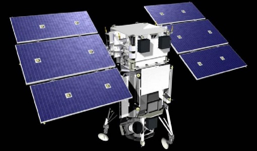
WorldView-2 full archive and tasking
WorldView-2 high resolution optical products are available as part of the Maxar Standard Satellite Imagery products from the QuickBird, WorldView-1/-2/-3/-4, and GeoEye-1 satellites. All details about the data provision, data access conditions and quota assignment procedure are described into the Terms of Applicability available in Resources section. In particular, WorldView-2 offers archive and tasking panchromatic products up to 0.46 m GSD resolution, and 4-Bands/8-Bands Multispectral products up to 1.84 m GSD resolution. Band Combination Data Processing Level Resolution Panchromatic and 4-bands Standard (2A)/View Ready Standard (OR2A) 15 cm HD, 30 cm HD, 30 cm, 40 cm, 50/60 cm View Ready Stereo 30 cm, 40 cm, 50/60 cm Map-Ready (Ortho) 1:12.000 Orthorectified 15 cm HD, 30 cm HD, 30 cm, 40 cm, 50/60 cm 8-bands Standard(2A)/View Ready Standard (OR2A) 30 cm, 40 cm, 50/60 cm View Ready Stereo 30 cm, 40 cm, 50/60 cm Map-Ready (Ortho) 1:12.000 Orthorectified 30 cm, 40 cm, 50/60 cm 4-Bands being an optional from: 4-Band Multispectral (BLUE, GREEN, RED, NIR1) 4-Band Pan-sharpened (BLUE, GREEN, RED, NIR1) 4-Band Bundle (PAN, BLUE, GREEN, RED, NIR1) 3-Bands Natural Colour (pan-sharpened BLUE, GREEN, RED) 3-Band Colored Infrared (pan-sharpened GREEN, RED, NIR1). 8-Bands being an optional from: 8-Band Multispectral (COASTAL, BLUE, GREEN, YELLOW, RED, RED EDGE, NIR1, NIR2) 8-Band Bundle (PAN, COASTAL, BLUE, GREEN, YELLOW, RED, RED EDGE, NIR1, NIR2). Native 30 cm and 50/60 cm resolution products are processed with MAXAR HD Technology to generate respectively the 15 cm HD and 30 cm HD products: the initial special resolution (GSD) is unchanged but the HD technique increases the number of pixels, improves the visual clarity and allows to obtain an aesthetically refined imagery with precise edges and well reconstructed details. As per ESA policy, very high-resolution imagery of conflict areas cannot be provided.
Data - Project Proposal (Restrained)

WorldView-2 European Cities
ESA, in collaboration with European Space Imaging, has collected this WorldView-2 dataset covering the most populated areas in Europe at 40 cm resolution. The products have been acquired between July 2010 and July 2015. Spatial coverage: Check the spatial coverage of the collection on a map available on the Third Party Missions Dissemination Service.
Data - Fast Registration with approval (Restrained)
WorldView-1 full archive and tasking
WorldView-1 high resolution optical products are available as part of the Maxar Standard Satellite Imagery products from the QuickBird, WorldView-1/-2/-3/-4, and GeoEye-1 satellites. All details about the data provision, data access conditions and quota assignment procedure are described into the Terms of Applicability available in Resources section. In particular, WorldView-1 offers archive and tasking panchromatic products up to 0.50 m GSD resolution. Band Combination Data Processing Level Resolution Panchromatic Standard(2A)/View Ready STANDARD (OR2A) 50 cm, 30 cm HD View Ready Stereo 50 cm Map-Ready (Ortho) 1:12.000 Orthorectified 50 cm, 30 cm HD Native 50 cm resolution products are processed with MAXAR HD Technology to generate the 30 cm HD products: the initial special resolution (GSD) is unchanged but the HD technique increases the number of pixels and improves the visual clarity achieving aesthetically refined imagery with precise edges and well reconstructed details. As per ESA policy, very high-resolution imagery of conflict areas cannot be provided.
Data - Fast Registration with approval (Restrained)
WorldView ESA archive
The WorldView ESA archive is composed of products acquired by WorldView-1, -2, -3 and -4 satellites and requested by ESA supported projects over their areas of interest around the world Panchromatic, 4-Bands, 8-Bands and SWIR products are part of the offer, with the resolution at Nadir depicted in the table. Band Combination Mission GSD Resolution at Nadir GSD Resolution (20° off nadir) Panchromatic WV-1 50 cm 55 cm WV-2 46 cm 52 cm WV-3 31 cm 34 cm WV-4 31 cm 34 cm 4-Bands WV-2 1.84 m 2.4 m WV-3 1.24 m 1.38 m WV-4 1.24 m 1.38 m 8-Bands WV-2 1.84 m 2.4 m WV-3 1.24 m 1.38 m SWIR WV-3 3.70 m 4.10 m The 4-Bands includes various options such as Multispectral (separate channel for Blue, Green, Red, NIR1), Pan-sharpened (Blue, Green, Red, NIR1), Bundle (separate bands for PAN, Blue, Green, Red, NIR1), Natural Colour (pan-sharpened Blue, Green, Red), Coloured Infrared (pan-sharpened Green, Red, NIR). The 8-Bands being an option from Multispectral (COASTAL, Blue, Green, Yellow, Red, Red EDGE, NIR1, NIR2) and Bundle (PAN, COASTAL, Blue, Green, Yellow, Red, Red EDGE, NIR1, NIR2). The processing levels are: Standard (2A): normalised for topographic relief View Ready Standard: ready for orthorectification (RPB files embedded) View Ready Stereo: collected in-track for stereo viewing and manipulation (not available for SWIR) Map Scale (Ortho) 1:12,000 Orthorectified: additional processing unnecessary Spatial coverage: Check the spatial coverage of the collection on a map available on the Third Party Missions Dissemination Service. The following table summarises the offered product types EO-SIP Product Type Band Combination Processing Level Missions WV6_PAN_2A Panchromatic (PAN) Standard/View Ready Standard WorldView-1 and 4 WV6_PAN_OR Panchromatic (PAN) View Ready Stereo WorldView-1 and 4 WV6_PAN_MP Panchromatic (PAN) Map Scale Ortho WorldView-1 and 4 WV1_PAN__2A Panchromatic (PAN) Standard/View Ready Standard WorldView-2 and 3 WV1_PAN__OR Panchromatic (PAN) View Ready Stereo WorldView-2 and 3 WV1_PAN__MP Panchromatic (PAN) Map Scale Ortho WorldView-2 and 3 WV1_4B__2A 4-Band (4B) Standard/View Ready Standard WorldView-2, 3 and 4 WV1_4B__OR 4-Band (4B) View Ready Stereo WorldView-2, 3 and 4 WV1_4B__MP 4-Band (4B) Map Scale Ortho WorldView-2, 3 and 4 WV1_8B_2A 8-Band (8B) Standard/View Ready Standard WorldView-2 and 3 WV1_8B_OR 8-Band (8B) View Ready Stereo WorldView-2 and 3 WV1_8B_MP 8-Band (8B) Map Scale Ortho WorldView-2 and 3 WV1_S8B__2A SWIR Standard/View Ready Standard WorldView-3 WV1_S8B__MP SWIR Map Scale Ortho WorldView-3 As per ESA policy, very high-resolution imagery of conflict areas cannot be provided.
Data - Data Description
TropForest - ALOS, GEOSAT-1 & KOMPSAT-2 optical coverages over tropical forests
The objective of the ESA TropForest project was to create a harmonised geo-database of ready-to-use satellite imagery to support 2010 global forest assessment performed by the Joint Research Centre (JRC) of the European Commission and by the Food and Agriculture Organization (FAO). Assessments for year 2010 were essential for building realistic deforestation benchmark rates at global to regional levels. To reach this objective, the project aimed to create a harmonised ortho-rectified/pre-processed imagery geo-database based on satellite data acquisitions (ALOS AVNIR-2, GEOSAT-1 SLIM6, KOMPSAT-2 MSC) performed during year 2009 and 2010, for the Tropical Latin America (excluding Mexico) and for the Tropical South and Southeast Asia (excluding China), resulting in 1971 sites located at 1° x 1° geographical lat/long intersections. The project finally delivered 1866 sites (94.7% of target) due to cloud coverages too high for missing sites. Spatial coverage: Check the spatial coverage of the collection on a map available on the Third Party Missions Dissemination Service.
Data - Project Proposal (Restrained)
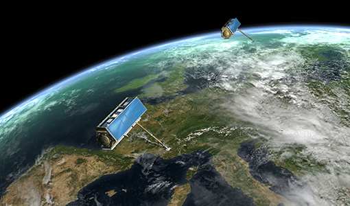
TerraSAR-X/TanDEM-X full archive and tasking
TerraSAR-X/TanDEM-X full archive and new tasking products can be acquired in six image modes with flexible resolutions (from 0.25 m to 40 m) and scene sizes and are provided in different packages: Staring SpotLight (basic, Interferometric pack, and Maritime pack) High Resolution SpotLight (basic, Interferometric pack, and Maritime pack) SpotLight (basic, Interferometric pack, and Maritime pack) StripMap (basic, Interferometric pack, and Maritime pack) ScanSAR (basic and Maritime pack) Wide ScanSAR (basic and Maritime pack) Product Overview Products SAR-ST SAR-HS SAR-SL SAR-SM SAR-SC SAR-WS Instrument mode Staring Spotlight High Resolution SpotLight SpotLight StripMap ScanSAR Wide ScanSAR Available resolutions (up to) 0.25 m 1 m 2 m 3 m 18 m 40 m Scene size 4x3.7 km2 10x5 km2 10x10 km2 30x50 km2 (up to 30x1650) 100x150 km2 (up to 100x1650) 270x200 km2 (up to 270x1500) Available processing levels SSC (Single Look Slant Range Complex): azimuth - slant range (time domain) MGD (Multi Look Ground Range Detected): azimuth - ground range (without terrain correction) GEC (Geocoded Ellipsoid Corrected): map geometry with ellipsoidal corrections only (no terrain correction performed) EEC (Enhanced Ellipsoid Corrected): map geometry with terrain correction, using a DEM Format SSC: DLR-defined COSAR binary MGD: GeoTiff GEC: GeoTiff EEC: GeoTiff Spatial coverage Worldwide Interferometry package InSAR-ST, InSAR-HS, InSAR-SL, InSAR-SM Only SSC At least five ordered scenes within six months from first order N/A N/A Maritime Monitoring package MmSAR-ST, MmSAR-HS, MmSAR-SL, MmSAR-SM, MmSAR-SC, MmSAR-WS Only SSC, MGD, GEC At least 75% of the scene area is water More than five ordered scenes in three months The following WorldDEM products can be requested: Products Description WorldDEMcore WorldDEMcore is output of interferometric processing of StripMap data pairs without any post-processing WorldDEMTM WorldDEMTM is produced based on WorldDEMcore, representing the surface of the Earth (including buildings, infrastructure and vegetation). Hydrological consistency is ensured WorldDEM DTM In additional editing steps, WorldDEMTMis transformed into a Digital Terrain Model (DTM) representing bare Earth elevation WorldDEM Bundle Includes WorldDEMTM, WorldDEM DTM, and Quality Layers The main specifications of the WorldDEM products are: Horizontal Coordinate Reference System: World Geodetic System 1984 (WGS84-G1150) Vertical Coordinate Reference System: Earth Gravitational Model 2008 (EGM2008) Absolute Horizontal Accuracy: <6 m Vertical Accuracy: 2 m Relative, 4 m Absolute Quality Layers (including water body mask) can be requested as an option with the WorldDEM and WorldDEM DTM Auxiliary Layers are delivered together with the WorldDEMcore product As per ESA policy, very high-resolution data over conflict areas cannot be provided.
Data - Fast Registration with approval (Restrained)
TerraSAR-X ESA archive
The TerraSAR-X ESA archive collection consists of TerraSAR-X and TanDEM-X products requested by ESA supported projects over their areas of interest around the world. The dataset regularly grows as ESA collects new products over the years. TerraSAR-X/TanDEM-X Image Products can be acquired in 6 image modes with flexible resolutions (from 0.25m to 40m) and scene sizes. Thanks to different polarimetric combinations and processing levels the delivered imagery can be tailored specifically to meet the requirements of the application. The following list delineates the characteristics of the SAR imaging modes that are disseminated under ESA Third Party Missions (TPM). StripMap (SM): Resolution 3 m, Scene size 30x50 km2 (up to 30x1650 km2) SpotLight (SL): Resolution 2 m, Scene size 10x10 km2 Staring SpotLight (ST): Resolution 0.25m, Scene size 4x3.7 km2 High Resolution SpotLight (HS): Resolution 1 m, Scene size 10x5 km2 ScanSAR (SC): Resolution 18 m, Scene size 100x150 km2 (up to 100x1650 km2) Wide ScanSAR (WS): Resolution 40 m, Scene size 270x200 km2 (up to 270x1500 km2) The following list briefly delineates the available processing levels for the TerraSAR-X dataset: SSC (Single Look Slant Range Complex) in DLR-defined COSAR binary format MGD (Multi Look Ground Range Detected) in GeoTiff format • GEC (Geocoded Ellipsoid Corrected) in GeoTiff format EEC (Enhanced Ellipsoid Corrected in GeoTiff format Spatial coverage: Check the spatial coverage of the collection on a map available on the Third Party Missions Dissemination Service. As per ESA policy, very high-resolution data over conflict areas cannot be provided.
Data - Fast Registration with immediate access (Open)
TanSat AGCS and CAPI products
The Atmospheric Carbon-dioxide Grating Spectrometer (ACGS) instrument is pushbroom spectrometer operating in NIR and SWIR bands which allows the measuring of CO2 mole fraction. The available ACGS products have a temporal coverage between March 2017 and January 2020 (not all days included in the time frame): L1A DS: Sample Dark Calibration sample product L1A GL: Sample Glint Sample products L1A LS: Sample Lamp Calibration sample product L1A ND: Principal-Plane Nadir Sample product L1A ZS: Sample Z-Axis Solar Calibration Sample L1B CAL DS: Sample Dark Calibration product L1B CAL LS: Sample Lamp Calibration product L1B CAL ZS: Sample Z-Axis Solar Calibration product L1B SCI GL: Sample Glint Science product L1B SCI ND: Principal-Plane Nadir Science product. The Cloud Aerosol Polarization Imager (CAPI) is a pushbroom radiometer in VIS, NIR and SWIR bands for the observation of aerosols and clouds optical properties. The CAPI products are available in a time range from July 2019 and January 2020 (not all days included in the time frame): L1A ND: Principal-Plane Nadir product L1B ND 1000M: Principal-Plane Nadir products at 1000 m resolution (1375 nm, 1640 nm) L1B ND 250M: Principal-Plane Nadir products at 250 m resolution (380 nm, 670 nm, 870 nm) L1B ND GEOQK: Principal-Plane Nadir georeferenced at 250 m resolution L1B ND GEO1K: Principal-Plane Nadir georeferenced at 1000 m resolution L1B ND OBC: Principal-Plane Nadir on-board calibrator product L2 ND CLM: Principal-Plane Nadir cloud flag product.
Data - Campaigns (Open)
SnowLab-NG
The overall objective of the SnowLab-NG activity was to provide a comprehensive multi-frequency, multi-polarisation, multi-temporal dataset and active and passive microwave measurements over snow-covered grounds.
Data - External Data (Restrained)
SciSat-1: ACE-FTS and MAESTRO
SCISAT-1 data aim at monitoring and analysing the chemical processes that control the distribution of ozone in the upper troposphere and stratosphere. It provides acquisitions from the two instruments MAESTRO and ACE-FTS. MAESTRO: Measurement of Aerosol Extinction in the Stratosphere and Troposphere Retrieved by Occultation. Dual-channel optical spectrometer in the spectral region of 285-1030 nm. The objective is to measure ozone, nitrogen dioxide and aerosol/cloud extinction (solar occultation measurements of atmospheric attenuation during satellite sunrise and sunset with the primary objective of assessing the stratospheric ozone budget). Solar occultation spectra are being used for retrieving vertical profiles of temperature and pressure, aerosols, and trace gases (O3, NO2, H2O, OClO, and BrO) involved in middle atmosphere ozone distribution. The use of two overlapping spectrometers (280 - 550 nm, 500 - 1030 nm) improves the stray-light performance. The spectral resolution is about 1-2 nm. ACE-FTS: Fourier Transform Spectrometer. The objective is to measure the vertical distribution of atmospheric trace gases, in particular of the regional polar O3 budget, as well as pressure and temperature (derived from CO2 lines). The instrument is an adapted version of the classical sweeping Michelson interferometer, using an optimised optical layout. The ACE-FTS measurements are recorded every 2 s. This corresponds to a measurement spacing of 2-6 km which decreases at lower altitudes due to refraction. The typical altitude spacing changes with the orbital beta angle. For historical reasons, the retrieved results are interpolated onto a 1 km "grid" using a piecewise quadratic method. For ACE-FTS version 1.0, the results were reported only on the interpolated grid (every 1 km from 0.5 to 149.5 km). For versions 2.2, both the "retrieval" grid and the "1 km" grid profiles are available. SCISAT-1 collection provides ACE-FTS and MAESTRO Level 2 Data. As of today, ACE-FTS products are available in version 4.1, while MAESTRO products are available in version 3.13.
Data - Campaigns (Open)
SARSimHT
The main objective of “SARSimHT – Airborne SAR experiment to simulate Hydroterra data” was to demonstrate the image formation process of Hydroterra through the exploitation of a repeat-pass hyper-temporal airborne SAR image stack acquired over short time intervals representative of the Hydroterra mission.
Data - Campaigns (Open)
ROVE (1975-1981)
The Dutch research team ROVE (Radar Observation on Vegetation), funded by the remote sensing organization NIWARS, started in 1974 to investigate the scattering of microwaves by crops and soils, in order to help interpretation of radar imagery.
Data - Project Proposal (Restrained)
ResourceSat-2 full archive and tasking
ResourceSat-2 (also known as IRS-R2) archive and tasking products are available as below: Sensor Type Resolution (m) Coverage (km x km) System or radiometrically corrected Ortho corrected (DN) Ortho corrected (TOA reflectance) Neustralitz archive Global archive LISS-IV Mono-Chromatic 5 70 x 70 X X 2014 – 2011 - LISS-III Multi-spectral 20 140 x 140 X X X AWiFS Multi-spectral 60 370 x 370 X X X Note: LISS-IV: Mono-Chromatic, the band is selectable. In practice the red is used. For LISS-IV MN and LISS-III ortho corrected: If unavailable, user has to supply ground control information and DEM in suitable quality. For AWiFS ortho corrected: service based on in house available ground control information and DEM. The products are available as part of the GAF Imagery products from the Indian missions: IRS-1C, IRS-1D, CartoSat-1 (IRS-P5), ResourceSat-1 (IRS-P6) and ResourceSat-2 (IRS-R2) missions. 'ResourceSat-2 archive and tasking' collection has worldwide coverage: for data acquired over Neustrelitz footprint, the users can browse the EOWEB GeoPortal catalogue to search archived products; worldwide data (out the Neustrelitz footprint) can be requested by contacting GAF user support to check the readiness since no catalogue is not available. All details about the data provision, data access conditions and quota assignment procedure are described in the Terms of Applicability.
Data - Project Proposal (Restrained)
ResourceSat-1/IRS-P6 full archive
ResourceSat-1 (also known as IRS-P6) archive products are available as below: Sensor Type Resolution (m) Coverage (km x km) System or radiometrically corrected Ortho corrected (DN) Neustralitz archive Global archive LISS-IV Mono-Chromatic 5 70 x 70 X X 2004 – 2010 2003 - 2013 LISS-III Multi-spectral 20 140 x 140 X X 2004 – 2013 2003 - 2013 AWiFS Multi-spectral 60 370 x 370 X X 2004 – 2013 2003 - 2013 Note: LISS-IV: Mono-Chromatic, the band is selectable. In practice the red is used. For LISS-IV MN and LISS-III ortho corrected: If unavailable, user has to supply ground control information and DEM in suitable quality. For AWiFS ortho corrected: service based on in house available ground control information and DEM. The products are available as part of the GAF Imagery products from the Indian missions: IRS-1C, IRS-1D, CartoSat-1 (IRS-P5), ResourceSat-1 (IRS-P6) and ResourceSat-2 (IRS-R2) missions. 'ResourceSat-1 archive' collection has worldwide coverage: for data acquired over Neustrelitz footprint, the users can browse the EOWEB GeoPortal catalogue to search archived products; worldwide data (out the Neustrelitz footprint) can be requested by contacting GAF user support to check the readiness since no catalogue is not available. All details about the data provision, data access conditions and quota assignment procedure are described in the Terms of Applicability.
Data - Fast Registration with approval (Restrained)
RADARSAT-2 ESA archive
The RADARSAT-2 ESA archive collection consists of RADARSAT-2 products requested by ESA supported projects over their areas of interest around the world. The dataset regularly grows as ESA collects new products over the years. Following Beam modes are available: Standard, Wide Swath, Fine Resolution, Extended Low Incidence, Extended High Incidence, ScanSAR Narrow and ScanSAR Wide. Standard Beam Mode allows imaging over a wide range of incidence angles with a set of image quality characteristics which provides a balance between fine resolution and wide coverage, and between spatial and radiometric resolutions. Standard Beam Mode operates with any one of eight beams, referred to as S1 to S8, in single and dual polarisation . The nominal incidence angle range covered by the full set of beams is 20 degrees (at the inner edge of S1) to 52 degrees (at the outer edge of S8). Each individual beam covers a nominal ground swath of 100 km within the total standard beam accessibility swath of more than 500 km. Beam Mode Product Nominal Resolution (metres) Nominal Pixel Spacing Range x Azimuth (metres) Resolution Range x Azimuth (metres) Nominal Scene Size Range x Azimuth (kilometres) Range of Angle of Incidence (degrees) Number of Looks Range x Azimuth Polarisations Options Standard SLC 25 8.0 or 11.8 x 5.1 9.0 or 13.5 x 7.7 100 x 100 20 - 52 1 x 1 Single Pol HH or VV or HV or VH - or - Dual HH + HV or VV + VH SGX 8.0 x 8.0 26.8 - 17.3 x 24.7 1 x 4 SGF 12.5 x 12.5 SSG, SPG Wide Swath Beam Mode allows imaging of wider swaths than Standard Beam Mode, but at the expense of slightly coarser spatial resolution. The three Wide Swath beams, W1, W2 and W3, provide coverage of swaths of approximately 170 km, 150 km and 130 km in width respectively, and collectively span a total incidence angle range from 20 degrees to 45 degrees. Polarisation can be single and dual. Beam Mode Product Nominal Resolution (metres) Nominal Pixel Spacing Range x Azimuth (metres) Resolution Range x Azimuth (metres) Nominal Scene Size Range x Azimuth (kilometres) Range of Angle of Incidence (degrees) Number of Looks Range x Azimuth Polarisations Options Wide SLC 30 11.8 x 5.1 13.5 x 7.7 150 x 150 20 - 45 1 x 1 Single: Pol HH or VV or HV or VH - or - Dual: HH + HV or VV + VH SGX 10 x 10 40.0 - 19.2 x 24.7 1 x 4 SGF 12.5 x 12.5 SSG, SPG Fine Resolution Beam Mode is intended for applications which require finer spatial resolution. Products from this beam mode have a nominal ground swath of 50 km. Nine Fine Resolution physical beams, F23 to F21, and F1 to F6 are available to cover the incidence angle range from 30 to 50 degrees. For each of these beams, the swath can optionally be centred with respect to the physical beam or it can be shifted slightly to the near or far range side. Thanks to these additional swath positioning choices, overlaps of more than 50% are provided between adjacent swaths. RADARSAT-2 can operate in single and dual polarisation for this beam mode. Beam Mode Product Nominal resolution (metres) Nominal Pixel Spacing Range x Azimuth (metres) Resolution Range x Azimuth (metres) Nominal Scene Size Range x Azimuth (kilometres) Range of Angle of Incidence (degrees) Number of Looks Range x Azimuth Polarisations Options Fine SLC 8 4.7 x 5.1 5.2 x 7.7 50 x 50 30 - 50 1 x 1 Single: Pol HH or VV or HV or VH - or - Dual: HH + HV or VV + VH SGX 3.13 x 3.13 10.4 - 6.8 x 7.7 1 x 1 SGF 6.25 x 6.25 SSG, SPG In the Extended Low Incidence Beam Mode, a single Extended Low Incidence Beam, EL1, is provided for imaging in the incidence angle range from 10 to 23 degrees with a nominal ground swath coverage of 170 km. Some minor degradation of image quality can be expected due to operation of the antenna beyond its optimum scan angle range. Only single polarisation is available. Beam Mode Product Nominal resolution (metres) Nominal Pixel Spacing Range x Azimuth (metres) Resolution Range x Azimuth (metres) Nominal Scene Size Range x Azimuth (kilometres) Range of Angle of Incidence (degrees) Number of Looks Range x Azimuth Polarisations Options Extended Low SLC 25 8.0 x 5.1 9.0 x 7.7 170 x 170 10 - 23 1 x 1 Single: HH SGX 10.0 x 10.0 52.7 - 23.3 x 24.7 1 x 4 SGF 12.5 x 12.5 SSG, SPG In the Extended High Incidence Beam Mode, six Extended High Incidence Beams, EH1 to EH6, are available for imaging in the 49 to 60 degree incidence angle range. Since these beams operate outside the optimum scan angle range of the SAR antenna, some degradation of image quality, becoming progressively more severe with increasing incidence angle, can be expected when compared with the Standard Beams. Swath widths are restricted to a nominal 80 km for the inner three beams, and 70 km for the outer beams. Only single polarisation available. Beam Mode Product Nominal resolution (metres) Nominal Pixel Spacing Range x Azimuth (metres) Resolution Range x Azimuth (metres) Nominal Scene Size Range x Azimuth (kilometres) Range of Angle of Incidence (degrees) Number of Looks Range x Azimuth Polarisations Options Extended High SLC 25 11.8 x 5.1 13.5 x 7.7 75 x 75 49 - 60 1 x 1 Single Pol HH SGX 8.0 x 8.0 18.2 - 15.9 x 24.7 1 x 4 SGF 12.5 x 12.5 SSG, SPG ScanSAR Narrow Beam Mode provides coverage of a ground swath approximately double the width of the Wide Swath Beam Mode swaths. Two swath positions with different combinations of physical beams can be used: SCNA, which uses physical beams W1 and W2, and SCNB, which uses physical beams W2, S5, and S6. Both options provide coverage of swath widths of about 300 km. The SCNA combination provides coverage over the incidence angle range from 20 to 39 degrees. The SCNB combination provides coverage over the incidence angle range 31 to 47 degrees. RADARSAT-2 can operate in single and dual polarisation for this beam mode. Beam Mode Product Nominal resolution (metres) Nominal Pixel Spacing Range x Azimuth (metres) Resolution Range x Azimuth (metres) Nominal Scene Size Range x Azimuth (kilometres) Range of Angle of Incidence (degrees) Number of Looks Range x Azimuth Polarisations Options ScanSAR Narrow SCN, SCF, SCS 20 25 x 25 81 - 38 x 40 - 70 300 x 300 20 - 46 2 x 2 Single Co or Cross: HH or VV or HV or VH - or - Dual: HH + HV or VV + VH ScanSAR Wide Beam Mode provides coverage of a ground swath approximately triple the width of the Wide Swath Beam Mode swaths. Two swath positions with different combinations of physical beams can be used: SCWA, which uses physical beams W1, W2, W3, and S7, and SCWB, which uses physical beams W1, W2, S5 and S6. The SCWA combination allows imaging of a swath of more than 500 km covering an incidence angle range of 20 to 49 degrees. The SCWB combination allows imaging of a swath of more than 450 km covering the incidence angle. Polarisation can be single and dual. Beam Mode Product Nominal resolution (metres) Nominal Pixel Spacing Range x Azimuth (metres) Resolution Range x Azimuth (metres) Nominal Scene Size Range x Azimuth (kilometres) Range of Angle of Incidence (degrees) Number of Looks Range x Azimuth Polarisations Options ScanSAR Wide SCW, SCF, SCS 100 50 x 50 163 - 73 x 78 - 106 500 x 500 20 - 49 4 x 2 Single Co or Cross: HH or VV or HV or VH - or - Dual: HH + HV or VV + VH These are the different products : SLC (Single Look Complex): Amplitude and phase information is preserved. Data is in slant range. Georeferenced and aligned with the satellite track SGF (Path Image): Data is converted to ground range and may be multi-look processed. Scene is oriented in direction of orbit path. Georeferenced and aligned with the satellite track. SGX (Path Image Plus): Same as SGF except processed with refined pixel spacing as needed to fully encompass the image data bandwidths. Georeferenced and aligned with the satellite track SSG(Map Image): Image is geocorrected to a map projection. SPG (Precision Map Image): Image is geocorrected to a map projection. Ground control points (GCP) are used to improve positional accuracy. SCN(ScanSAR Narrow)/SCF(ScanSAR Wide) : ScanSAR Narrow/Wide beam mode product with original processing options and metadata fields (for backwards compatibility only). Georeferenced and aligned with the satellite track SCF (ScanSAR Fine): ScanSAR product equivalent to SGF with additional processing options and metadata fields. Georeferenced and aligned with the satellite track SCS(ScanSAR Sampled) : Same as SCF except with finer sampling. Georeferenced and aligned with the satellite track. Spatial coverage: Check the spatial coverage of the collection on a map available on the Third Party Missions Dissemination Service.
Data - Project Proposal (Restrained)
RADARSAT-1 & 2 full archive and tasking
RADARSAT-1 products The Standard beam mode operates with any one of seven beam positions, referred to as S1 to S7. The nominal incidence angle range covered by the full set of Standard beams is from 20 degrees (at the inner edge of S1) to 49 degrees (at the outer edge of S7). Each individual beam covers a minimum ground swath of 100 km within the total 500 km accessibility swath of the full set of Standard beams. The nominal spatial resolution in the range direction is 26 m for S1 at near range to 20 m for S7 at far range. The nominal azimuth resolution is the same, 27 m, for all beam positions. The Wide beam modes are similar to the Standard beams except that the swath width achieved by this beam is 150 km rather than 100 km. As a result, only three Wide beams, W1, W2 and W3 are necessary to provide coverage of almost all of the 500 km swath range. They provide comparable resolution to the standard beam mode, though the increased ground swath coverage is obtained at the expense of a slight reduction in overall image quality. In the Fine beam mode the nominal azimuth resolution is 8.4 m, with range resolution 9.1 m to 7.8 m from F1 to F5. Since the radar operates with a higher sampling rate in this mode than in any of the other beam mode, the ground swath coverage has to be reduced to approximately 50 km in order to keep the downlink signal within its allocated bandwidth. Originally, five Fine beam positions, F1 to F5, were available to cover the far range of the swath with an incidence angle range from 37 to 47 degrees. By modifying timing parameters, 10 new positions have been added with offset ground coverage. Each original Fine beam position can either be shifted closer to or further away from Nadir. In Extended High beam mode six positions, EH1 to EH6, are available for collection of data in the 49 to 60 degree incidence angle range. Since this beam mode operates outside the optimum scan angle range of the SAR antenna, some minor degradation of image quality can be expected when compared with the Standard beam mode. Swath widths are restricted to a nominal 80 km for the inner three positions, and 70 km for the outer three positions. In Extended Low beam mode one position, EL1, is provided for imaging in the incidence angle range 10 to 23 degrees with nominal ground swath coverage of 170 km. As with the Extended High beam mode, some minor degradation of image quality can be expected due to operation of the antenna beyond its optimum elevation angle range. In ScanSAR mode, combinations of two, three or four single beams are used during data collection. Each beam is selected sequentially so that data is collected from a wider swath than possible with a single beam. The beam switching rates are chosen to ensure at least one "look" at the Earth's surface for each beam within the along track illumination time or dwell time of the antenna beam. In practice, the radar beam switching is adjusted to provide two looks per beam. The beam multiplexing inherent in ScanSAR operation reduces the effective sampling rate within each of the component beams; hence the increased swath coverage is obtained at the expense of spatial resolution. The ScanSAR Narrow mode combines two beams (incidence angle range of 20 to 39 degrees) or three beams (incidence angle from 31 to 46 degrees) and provides coverage of a nominal 300 km ground swath, with spatial resolution of 50 m. The ScanSAR Wide mode combines four beams, provides coverage of either 500 km (with incidence angle range of 20 to 49 degrees) or 450 km (incidence angle range from 20 to 46 degrees) nominal ground swaths depending on the beam combination. Beam Mode Product Ground coverage (km2) Nominal resolution (m) Polarisation ScanSAR wide SCW, SCF, SCS 500 x 500 100 Single and dual ScanSAR narrow SCN, SCF, SCS 300 x 300 60 Single and dual Wide SGF, SGX, SLC, SSG, SPG 150 x 150 24 Single and dual Standard SGF, SGX, SLC, SSG, SPG 100 x 100 24 Single Extended low SGF, SGX, SLC, SSG, SPG 170 x 170 24 Single Extended high SGF, SGX, SLC, SSG, SPG 75 x 75 24 Single Fine SGF, SGX, SLC, SSG, SPG 50 x 50 8 Single RADARSAT-2 products The Standard Beam Mode allows imaging over a wide range of incidence angles with a set of image quality characteristics which provides a balance between fine resolution and wide coverage, and between spatial and radiometric resolutions. Standard Beam Mode operates with any one of eight beams, referred to as S1 to S8. The nominal incidence angle range covered by the full set of beams is 20 degrees (at the inner edge of S1) to 52 degrees (at the outer edge of S8). Each individual beam covers a nominal ground swath of 100 km within the total standard beam accessibility swath of more than 500 km. The Wide Swath Beam Mode allows imaging of wider swaths than Standard Beam Mode, but at the expense of slightly coarser spatial resolution. The three Wide Swath beams, W1, W2 and W3, provide coverage of swaths of approximately 170 km, 150 km and 130 km in width respectively, and collectively span a total incidence angle range from 20 degrees to 45 degrees. The Fine Resolution Beam Mode is intended for applications which require finer spatial resolution. Products from this beam mode have a nominal ground swath of 50 km. Nine Fine Resolution physical beams, F23 to F21, and F1 to F6 are available to cover the incidence angle range from 30 to 50 degrees. For each of these beams, the swath can optionally be centred with respect to the physical beam or it can be shifted slightly to the near or far range side. Thanks to these additional swath positioning choices, overlaps of more than 50% are provided between adjacent swaths. In the Extended Low Incidence Beam Mode, a single Extended Low Incidence Beam, EL1, is provided for imaging in the incidence angle range from 10 to 23 degrees with a nominal ground swath coverage of 170 km. Some minor degradation of image quality can be expected due to operation of the antenna beyond its optimum scan angle range. In the Extended High Incidence Beam Mode, six Extended High Incidence Beams, EH1 to EH6, are available for imaging in the 49 to 60 degree incidence angle range. Since these beams operate outside the optimum scan angle range of the SAR antenna, some degradation of image quality, becoming progressively more severe with increasing incidence angle, can be expected when compared with the Standard Beams. Swath widths are restricted to a nominal 80 km for the inner three beams, and 70 km for the outer beams. ScanSAR Narrow Beam Mode provides coverage of a ground swath approximately double the width of the Wide Swath Beam Mode swaths. Two swath positions with different combinations of physical beams can be used: SCNA, which uses physical beams W1 and W2, and SCNB, which uses physical beams W2, S5, and S6. Both options provide coverage of swath widths of about 300 km. The SCNA combination provides coverage over the incidence angle range from 20 to 39 degrees. The SCNB combination provides coverage over the incidence angle range 31 to 47 degrees. ScanSAR Wide Beam Mode provides coverage of a ground swath approximately triple the width of the Wide Swath Beam Mode swaths. Two swath positions with different combinations of physical beams can be used: SCWA, which uses physical beams W1, W2, W3, and S7, and SCWB, which uses physical beams W1, W2, S5 and S6. The SCWA combination allows imaging of a swath of more than 500 km covering an incidence angle range of 20 to 49 degrees. The SCWB combination allows imaging of a swath of more than 450 km covering the incidence angle. In the Standard Quad Polarization Beam Mode, the radar transmits pulses alternately in horizontal (H) and vertical (V) polarisations, and receives the return signals from each pulse in both H and V polarisations separately but simultaneously. This beam mode therefore enables full polarimetric (HH+VV+HV+VH) image products to be generated. The Standard Quad Polarization Beam Mode operates with the same pulse bandwidths as the Standard Beam Mode. Products with swath widths of approximately 25 km can be obtained covering any area within the region from an incidence angle of 18 degrees to at least 49 degrees. The Wide Standard Quad Polarization Beam Mode operates the same way as the Standard Quad Polarization Beam Mode but with higher data acquisition rates, and offers wider swaths of approximately 50 km at equivalent spatial resolution. 21 beams are available covering any area from 18 degrees to 42 degrees, ensuring overlaps of about 50% between adjacent swaths. The Fine Quad Polarization Beam Mode provides full polarimetric imaging with the same spatial resolution as the Fine Resolution Beam Mode. Fine Quad Polarization Beam Mode products with swath widths of approximately 25 km can be obtained covering any area within the region from an incidence angle of 18 degrees to at least 49 degrees. The Wide Fine Quad Polarization Beam Mode operates the same way as the Fine Quad Polarization Beam Mode but with higher data acquisition rates, and offers a wider swath of approximately 50 km at equivalent spatial resolution. 21 beams are available covering any area from 18 degrees to 42 degrees, ensuring overlaps of about 50% between adjacent swaths. The Multi-Look Fine Resolution Beam Mode covers the same swaths as the Fine Resolution Beam Mode. Products with multiple looks in range and azimuth are generated at approximately the same spatial resolution as Fine Resolution Beam mode products, but with multiple looks and therefore improved radiometric resolution. Single look products are generated at finer spatial resolutions than Fine Resolution Beam Mode products. In order to obtain the multiple looks without a reduction in swath width, this beam mode operates with higher data acquisition rates and noise levels than Fine Resolution Beam Mode. As with the Fine Resolution Beam Mode, nine physical beams are available to cover the incidence angle range from 30 to 50 degrees, and additional near and/or far range swath positioning choices are available to provide additional overlap. The Wide Multi-Look Fine Resolution Beam Mode offers a wider coverage alternative to the regular Multi-Look Fine Beam Mode, while preserving the same spatial and radiometric resolution, but at the expense of higher data compression ratios (which leads to higher signal-dependent noise levels). The nominal swath width is 90 km compared to 50 km for the Multi-Look Fine Beam Mode. The nine physical beams are the same as in the Multi-Look Fine Beam Mode, covering incidence angles from approximately 30 to 50 degrees, but the additional near and far range swath positioning choices available in the Multi-Look Fine Beam Mode are not needed because the beam centered swaths are wide enough to overlap by more than 50%. The Ultra-Fine Resolution Beam Mode is intended for applications which require very high spatial resolution. The set of Ultra-Fine Resolution Beams cover any area within the incidence angle range from 20 to 50 degrees (soon to be extended to 54 degrees). Each beam within the set images a swath width of at least 20 km. The Wide Ultra-Fine Resolution Beam Mode provides the same spatial resolution as the Ultra-Fine mode as well as wider coverage, but at the expense of higher data compression ratios (which leads to higher signal-dependent noise levels). The set of Wide Ultra-Fine Resolution Beams cover any area within the incidence angle range from 30 to 50 degrees. Each beam within the set images a swath width of approximately 50 km. The Wide Fine Resolution Beam Mode is intended for applications which require both a finer spatial resolution and a wide swath. Products from this beam mode have a nominal ground swath equivalent to the ones offered by the Wide Swath Beam Mode (170 km, 150 km and 120 km) and a spatial resolution equivalent to the ones offered by the Fine Resolution Beam Mode, at the expense of somewhat higher noise levels. Three Wide Fine Resolution beam positions, F0W1 to F0W3 are available to cover the incidence angle range from 20 to 45 degrees. The Extra-Fine Resolution Beam Mode nominally provides similar swath width and incidence angle coverage as the Wide Fine Beam Mode, at even finer resolutions, but with higher data compression ratios and noise levels. The four Extra-Fine beams provide coverage of swaths of approximately 160 km, 124 km, 120 km and 108 km in width respectively, and collectively span a total incidence angle range from 22 to 49 degrees. This beam mode also offers additional optional processing parameter selections that allow for reduced-bandwidth single-look products, 4-look, and 28-look products. In Spotlight Beam Mode, the beam is steered electronically in order to dwell on the area of interest over longer aperture times, which allows products to be processed to finer azimuth resolution than in other modes. Unlike in other modes, Spotlight images are of fixed size in the along track direction. The set of Spotlight beams cover any area within the incidence angle range from 20 to 50 degrees (soon to be extended to 54 degrees). Each beam within the set images a swath width of at least 18 km. Beam Mode Product Nominal Pixel Spacing [Range x Azimuth] (metres) Nominal Resolution (metres) Resolution [Range x Azimuth] (metres) Nominal Scene Size [Range x Azimuth] (kilometres) Range of Angle of Incidence [Range] (degrees) Number of Looks [Range x Azimuth] Polarisations Options Spotlight SLC 1.3 x 0.4 <1 1.6 x 0.8 18 x 8 20 to 54 1 x 1 Single Co or Cross (HH or VV or HV or VH) SGX 1 or 0.8 x 1/3 4.6 - 2.0 x 0.8 SGF 0.5 x 0.5 SSG, SPG Ultra-fine SLC 1.3 x 2.1 3 1.6 x 2.8 20 x 20 20 to 54 1 x 1 Single Co or Cross (HH or VV or HV or VH) SGX 1 x 1 or 0.8 x 0.8 3.3 – 2.1 x 2.8 SGF 1.56 x 1.56 SSG, SPG Wide Ultra-fine SLC 1.3 x 2.1 3 3.1 x 4.6 50 x 50 29 to 50 1 x 1 Single Co or Cross (HH or VV or HV or VH) SGX 1 x 1 3.3 - 2.1 x 2.8 SGF 1.56 x 1.56 SSG, SPG Multi-look fine SLC 2.7 x 2.9 8 3.1 x 4.6 50 x 50 30 to 50 1 x 1 Single Co or Cross (HH or VV or HV or VH) SGX 3.13 x 3.13 10.4 - 6.8 x 7.6 2 x 2 SGF 6.25 x 6.25 SSG, SPG Wide Multi-look fine SLC 2.7 x 2.9 8 3.1 x 4.6 90 x 50 29 to 50 1 x 1 Single Co or Cross (HH or VV or HV or VH) SGX 3.13 x 3.13 10.8 - 6.8 x 7.6 2 x 2 SGF 6.25 x 6.25 SSG, SPG Extra-fine SLC (Full resolution) 2.7 x 2.9 5 3.1 x 4.6 125 x 125 22 to 49 1 x 1 Single Co or Cross (HH or VV or HV or VH) SLC (fine resolution) 4.3 x 5.8 5.2 x 7.6 SLC (standard resolution) 7.1 x 5.8 8.9 x 7.6 SLC (wide resolution) 10.6 x 5.8 13.3 x 7.6 SGX (1 look) 2.0 x 2.0 8.4 – 4.1 x 4.6 SGX (4 looks) 3.13 x 3.13 14 – 6.9 x 7.6 2 x 2 SGX (28 looks) 5.0 x 5.0 24 - 12 x 23.5 4 x 7 SGF (1 look) 3.13 x 3.13 8.4 - 4.1 x 4.6 1 x 1 SGF (4 looks) 6.25 x 6.25 14 - 6.9 x 7.6 2 x 2 SGF (28 looks) 8.0 x 8.0 24 - 12 x 23.5 4 x 7 SSG, SPG 3.13 x 3.13 8.4 - 4.1 x 4.6 1 x 1 Fine SLC 4.7 x 5.1 8 5.2 x 7.7 50 x 50 30 to 50 1 x 1 Single Co or Cross (HH or VV or HV or VH) or Dual (HH+HV or VV+VH) SGX 3.13 x 3.13 10.4 – 6.8 x 7.7 SGF 6.25 x 6.25 SSG, SPG Wide Fine SLC 4.7 x 5.1 8 5.2 x 7.7 150 x 150 20 to 45 1 x 1 Single Co or Cross (HH or VV or HV or VH) or Dual (HH+HV or VV+VH) SGX 3.13 x 3.13 14.9 - 7.3 x 7.7 SGF 6.25 x 6.25 SSG, SPG Standard SLC 8.0 or 11.8 x 5.1 25 9.0 or 13.5 x 7.7 100 x 100 20 - 52 1 x 1 Single Co or Cross (HH or VV or HV or VH) or Dual (HH+HV or VV+VH) SGX 8 x 8 26.8 - 17.3 x 24.7 1 x 4 SGF 12.5 x 12.5 SSG, SPG Wide SLC 11.8 x 5.1 30 13.5 x 7.7 150 x 150 20 - 45 1 x 1 Single Co or Cross (HH or VV or HV or VH) or Dual (HH+HV or VV+VH) SGX 10 x 10 40.0 - 19.2 x 24.7 1 x 4 SGF 12.5 x 12.5 SSG, SPG Extended High SLC 11.8 x 5.1 25 13.5 x 7.7 75 x 75 49 - 60 1 x 1 Single (HH only) SGX 8 x 8 18.2 - 15.9 x 24.7 1 x 4 SGF 12.5 x 12.5 SSG, SPG Extended Low SLC 8.0 x 5.1 25 9.0 x 7.7 170 x 170 10 - 23 1 x 1 Single (HH only) SGX 10 x 10 52.7 – 23.3 x 24.7 1 x 4 SGF 12.5 x 12.5 SSG, SPG Fine Quad-Pol SLC 4.7 x 5.1 8 5.2 x 7.6 25 x 25 18 - 49 1 x 1 Quad (HH+VV+HV+VH) SGX 3.13 x 3.13 16.5 – 6.8 x 7.6 1 x 1 SSG, SPG Wide Fine Quad-Pol SLC 4.7 x 5.1 8 5.2 x 7.6 50 x 25 18 - 42 1 x 1 Quad (HH+VV+HV+VH) SGX 3.13 x 3.13 17.3–7.8 x 7.6 SSG, SPG Standard Quad-Pol SLC 8 or 11.8 x 5.1 25 9.0 or 13.5 x 7.6 25 x 25 18 - 49 1 x 1 Quad (HH+VV+HV+VH) SGX 8 x 3.13 28.6 – 17.7 x 7.6 SSG, SPG Wide Standard Quad-Pol SLC 8 or 11.8 x 5.1 25 9.0 or 13.5 x 7.6 50 x 25 18 - 42 1 x 1 Quad (HH+VV+HV+VH) SGX 8 x 3.13 30.0 –16.7 x 7.6 SSG, SPG ScanSAR Narrow SCN, SCF, SCS 25 x 25 50 81–38 x 40-70 300 x 300 20 to 46 2 x 2 Single Co or Cross (HH or VV or HV or VH) or Dual (HH+HV or VV+VH) ScanSAR Wide SCW, SCF, SCS 50 x 50 100 163-73 x 78-106 500 x 500 20 to 49 4 x 2 Single Co or Cross (HH or VV or HV or VH) or Dual (HH+HV or VV+VH) These are the different products : SLC (Single Look Complex): Amplitude and phase information is preserved. Data is in slant range. Georeferenced and aligned with the satellite track SGF (Path Image): Data is converted to ground range and may be multi-look processed. Scene is oriented in direction of orbit path. Georeferenced and aligned with the satellite track. SGX (Path Image Plus): Same as SGF except processed with refined pixel spacing as needed to fully encompass the image data bandwidths. Georeferenced and aligned with the satellite track SSG (Map Image): Image is geocorrected to a map projection. SPG (Precision Map Image): Image is geocorrected to a map projection. Ground control points (GCP) are used to improve positional accuracy. SCN (ScanSAR Narrow)/SCF(ScanSAR Wide) : ScanSAR Narrow/Wide beam mode product with original processing options and metadata fields (for backwards compatibility only). Georeferenced and aligned with the satellite track SCF (ScanSAR Fine): ScanSAR product equivalent to SGF with additional processing options and metadata fields. Georeferenced and aligned with the satellite track SCS (ScanSAR Sampled) : Same as SCF except with finer sampling. Georeferenced and aligned with the satellite track.
Data - Fast Registration with approval (Restrained)
QuickBird-2 ESA archive
The QuickBird-2 archive collection consists of QuickBird-2 products requested by ESA supported projects over their areas of interest around the world. The dataset regularly grows as ESA collects new products over the years. Panchromatic (up to 61 cm resolution) and 4-Bands (up to nominal value of 2.44 m resolution, reduced to 1.63 m when the orbit altitude was lowered to 300 km at the end of the mission) products are available. The 4-Bands includes various options such as Multispectral (separate channel for Blue, Green, Red, NIR1), Pan-sharpened (Blue, Green, Red, NIR1), Bundle (separate bands for PAN, Blue, Green, Red, NIR1), Natural Colour (pan-sharpened Blue, Green, Red), Coloured Infrared (pan-sharpened Green, Red, NIR1), Natural Colour / Coloured Infrared (3-Band pan-sharpened). The processing levels are: STANDARD (2A): normalised for topographic relief View Ready Standard (OR2A): ready for orthorectification View Ready Stereo: collected in-track for stereo viewing and manipulation Map-Ready (Ortho) 1:12,000 Orthorectified: additional processing unnecessary Map-Ready (Ortho) 1:15,000 Orthorectified: additional processing unnecessary Spatial coverage: Check the spatial coverage of the collection on a map available on the Third Party Missions Dissemination Service. The following table summarises the offered product types EO-SIP product type Band Combination Description BGI_PAN_2A Panchromatic (PAN) Panchromatic Standard/Panchromatic Ortho Ready Standard BGI_PAN_MP Panchromatic (PAN) Panchromatic Map Scale Ortho BGI_PAN_OR Panchromatic (PAN) Panchromatic Ortho Ready Stereo BGI_4B__2A 4-Band (4B) 4-Band Standard/4-band Ortho Ready Standard BGI_4B__MP 4-Band (4B) 4-Band Map Scale Ortho BGI_4B__OR 4-Band (4B) 4-Band Ortho Ready Stereo
Data - Project Proposal (Restrained)
QuickBird full archive
QuickBird high resolution optical products are available as part of the Maxar Standard Satellite Imagery products from the QuickBird, WorldView-1/-2/-3/-4, and GeoEye-1 satellites. All details about the data provision, data access conditions and quota assignment procedure are described into the Terms of Applicability available in Resources section. In particular, QuickBird offers archive panchromatic products up to 0.60 m GSD resolution and 4-Bands Multispectral products up to 2.4 m GSD resolution. Band Combination Data Processing Level Resolution Panchromatic and 4-bands Standard(2A)/View Ready Standard (OR2A) 15 cm HD, 30 cm HD, 30 cm, 40 cm, 50/60 cm View Ready Stereo 30 cm, 40 cm, 50/60 cm Map-Ready (Ortho) 1:12,000 Orthorectified 15 cm HD, 30 cm HD, 30 cm, 40 cm, 50/60 cm 4-Bands being an option from: 4-Band Multispectral (BLUE, GREEN, RED, NIR1) 4-Band Pan-sharpened (BLUE, GREEN, RED, NIR1) 4-Band Bundle (PAN, BLUE, GREEN, RED, NIR1) 3-Bands Natural Colour (pan-sharpened BLUE, GREEN, RED) 3-Band Colored Infrared (pan-sharpened GREEN, RED, NIR1) Natural Colour / Coloured Infrared (3-Band pan-sharpened) Native 30 cm and 50/60 cm resolution products are processed with MAXAR HD Technology to generate respectively the 15 cm HD and 30 cm HD products: the initial special resolution (GSD) is unchanged but the HD technique intelligently increases the number of pixels and improves the visual clarity achieving aesthetically refined imagery with precise edges and well reconstructed details.